This was a final project for an optics class EE 134 at Stanford. It was an open-ended project to make a fully functioning laser microphone–the class was geared to demonstrate optics and photonics in the lab, not necessarily electrical schematics. There are real commercial devices that use lasers to sense sound acoustics from glass surfaces. The hardest aspects of this sort of project were getting all the optics to line up and work properly. The final write-up is included here.
Abstract
A laser microphone was constructed and demonstrated. The laser was able to successfully detect audio vibrations and recover the signal in a useful form for processing. Electrical circuits provided amplification and filtering which improved signal quality. After recovery, the audio signal was output to a speaker. The system had a signal-to-noise ratio of 3.7 dB and recovered about 25% of the laser power at variable distances from 15 to 80 cm.
Introduction
Laser microphones are capable of detecting sound at distances and through mediums that traditional equipment cannot. Law enforcement or other surveillance experts employ many techniques and equipment in order to gather information. A traditional "bug" is an electronic device that is physically placed near or inside enclosures which transmits audio information via radio or other short-ranged frequencies. With the use of a laser, entry into a building in order to plant a bug is not necessary. Instead, only a direct line of sight to a window or other vibrating surface will suffice in order to sample and receive audio information.
Techniques demonstrated in this paper could also be employed to perform high sensitivity studies on any vibrating surface and need not be limited to audio frequencies. Laser vibrometry is a technique to measure the velocity of vibrating surfaces by detecting doppler shift in frequency. This approach detects phase shift of an interferometer instead of direct frequency modulation as used in this project.
Procedure and Results
Optical Stage
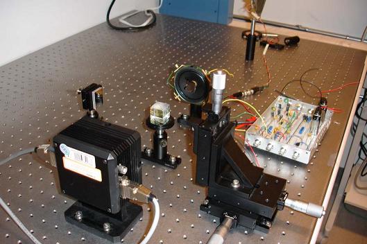
The optical stage directs laser light through a beam splitter. The forward path strikes a mirror which is mounted on a speaker head. The laser is directly modulated by the speaker by an audio signal. As the beam returns, it passes back through the beam splitter and is focused using an objective lens onto a photodiode. The second path which splits from the beam splitter is reflected back by a reference mirror and then recombined at the beam splitter with the first returning beam. In a true interferometric system, the second branch of the beam splitter is used as reference to detect the phase difference caused by the changing path length of the first branch. In this way, very small vibrations can be detected by examining the signal at the photodiode. Figure-1 illustrates the basic schematics of the optical design implemented.
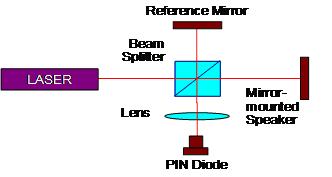
Fig. 1. Photo detector and beam splitter setup. Diagram of the optical components including: laser-mount, beam splitter, mirror-system and photodiode.
The laser used in this project operated at 1550nm. A laser wavelength of any size would be sufficient for the audio frequencies of this project. The size of the wavelength is only a concern to discern vibrations of the same order of magnitude in size. Infrared has the added benefit of being invisible which might be desirable for surveillance purposes.
Transmitter Circuit
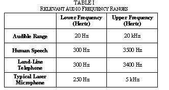
A full laser microphone system is designed to detect sound vibrations from glass or other surfaces. For the purposes of this project, the vibrating, reflective surface was chosen to be a mirror directly modulated by the output of an audio amplifier. An LM386 audio amplifier drove a speaker which had a small section of mirror adhered to the center of the speaker cone. Two different types of input signals were used during the course of the project. The first was a microphone which provided about 1 to 5mV of input and modulated the speaker with similar characteristics of a real-world system. The second type of input came from a function generator. The minimum voltage that this lab equipment could provide was 50mVpp. Instead of providing a low-voltage signal, the function generator was used to determine fidelity of the system at variable frequencies from 20 Hz to 1.5 kHz. It was found that about 200 Hz transmitted with the best fidelity.
The LM386 has a variable gain. This allows adjustment and regulation of voltages which were used to control the mirror-mounted, vibrating speaker cone. Although it is difficult to determine how far the speaker head was displaced, it is possible to record voltage swings at the output of the LM386. Increasing the gain of the transmitter system to 200 greatly improved signal integrity. High gain allows for the greatest displacement of the speaker cone and proved to be the easiest to detect at the photodiode.
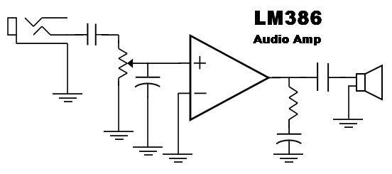
Fig. 2. LM386 Audio Amplifier circuit used to drive speaker cone. See attached schematic for values. Pins 1-8 may be used to set gain. Configuration had A = 200 set with a 10 uF capacitor. Without capacitance, the LM386 is set to unity gain.
The receiver circuit employed a ThorLabs diode. This diode was chosen due to acceptible switching rates at audio frequencies and lab availability. The diode was reverse biased with a 10k ohm resistor. Reverse biasing the photodiode across a resistor provided variable voltage into a receiver circuit which could then be filtered and amplified.
Receiver Circuit
The reciever circuit needed to receive the input of the photodiode and provide very low noise amplification and filtering. Another speaker system identical to Figure-2 provided sufficient audio amplification to port the signal to an external speaker. Two different designs were constructed to handle filtering and low-noise amplification. One designed used the TL5580 and another used the LT1677. Both of these opamps were chosen due to their specific abilities to peform well at low currents and with very noise-sensitive signals. The first design amplifies the incoming signal and then filters and amplifies the feedback back into the first opamp. The second design used two back-to-back butterworth filters which provide gain while simultaneously filtering the signal outside of a 20 Hz to 1.5 kHz range.
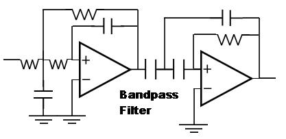
Fig. 3. Dual Two-pole Butterworth filters. Poles were set at 20Hz and 1.5kHz to make a bandpass. See attached schematic for values. Opamps were specifically chosen for low-noise, low-current properties.
After filtering, the signal was fed directly into another audio amplifier in order to drive an output speaker. This part of the circuit was identical to Figure-2.
Experimental Results
For this project the laser implemented was a Newport 1550 Semiconductor Laser source mounted with Thermo-Electric (TE) cooler and collimating lens. The Newport TE cooler controller and Newport precision current source helped control the laser and keep it calibrated at 18 degrees Celsius and 35mA. A simple battery-operated power meter and Thor Labs photo detector were used to measure the output power.
To setup the project required collimating the laser beam and employing optical positioning stages and stage mounts. In order to suppress the negative interference effects, the distances to the mirrors on the separate branches were chosen to be integer multiple distances of wavelengths from the beam splitter. The photodiode was positioned by utilizing the XYZ positioning stages to allow for maximum laser coverage on the photo-sensitive area.
Distance versus power is the critical application of this system. Useful laser microphone systems need to maximize the distance in order to send a laser beam while maintaining signal strength. Measurements for this project were performed with a function generator at 50mVpp and at a frequency of 200 Hz. The results obtained are plotted in Figure-3 and Figure-4.
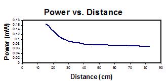
Fig. 3. Power versus distance. As expected, at longer distances, the power of the recovered signal decreased. 80 cm represents the maximum distance on the optical table on which this project was performed.
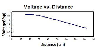
Fig. 4. Voltage versus Distance. The trend follows power as expected.
Signal to noise ratio (SNR) is a measure of the power of the signal over the power of background noise. At the photodiode before filtering, the laser microphone system exhibited a signal-to-noise ratio of 3.7 dB. There are many ways to improve this number by addressing enhancements in both the optical and electrical configuration.
Analysis and Discussion
Although ideal for limiting beam scattering and recovering a laser beam back from a surface, the mirror-mounted speaker surface is too ideal of a vibrating surface. A real world system would have to be able to recover a signal from poor reflective surfaces like glass windows at much greater distances.
Collimated laser beams do not stay coherent indefinitely. The spreading of a laser beam radius is given as a function of its beam size at its waist and wavelength. Additionally at extremely long distances, a laser beam is more likely to scatter off particles in the air.

Fig. 5. Beam Radius w(z) over some distance z; given starting beam radius w0 and wavelength lambda.
Improvements in optical capturing can be easily enhanced with lenses. The ability to capture light from a broadened beam radius is paramount in beam recovery. Telescopic lenses combined with an optical filter would provide a better means of recovering the signal and removing the noise before electrical components are used.
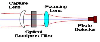
Fig. 6. Enhanced receiver with telescopic lens system. Optical filters can filter the signal optically and remove noise before it is injected into the electrical system.
The optical portion of the system could also be improved by employing a special beam-splitter. If a non-interferometric approach is desired, the beam splitter could be replaced by a special prism that splits the beam and sends both branches in the same direction. This ensures that after reflecting, both branches will have traveled the same distance and are identically modulated. For audio purposes this serves to enhance the direct audio modulation of the beam by using the entire power of the laser beam.
The gain provided for the transmitter circuit was considerably higher than practical levels. The vibrations caused by human speech on the surface of a window would provide a far smaller displacement and thus provide a much harder signal to recover. For similar systems and for detecting very small vibrations, a full interferometric system would be advisable.
It was found that the filtering opamps, although rated for low-noise and low-current, were still a significant source of noise in the system. A higher fidelity signal was attained by directly coupling the photodiode to the audio amplifier. Unfortunately a direct hook-up of this sort had the adverse effect of amplifying all parts of the signal including noise.
Conclusion
The design and analysis of a Laser Microphone based on the principle of laser frequency modulation was presented and experimentally characterized. The various tradeoffs between audio fidelity and distance to the target were explored through experiments. The final design showed acceptable performance capable of transmitting and receiving audio and processing through electronics. A signal-to-noise ratio of 3.7dB was accomplished, and for a variable distance of the mirror mounted speaker from 15 to 80cm 25% of the laser power was recovered.
Acknowledgement
The authors would like to thank to Prof. Olav Solgaard for teaching the course, "Photonics Laboratory" as well as the teaching assistants who directed laboratories and provided useful suggestions and support.
References
- "Laser Microphone," Williamson Labs, University of Wisconsin, http://www.williamson-labs.com/laser-mic.html, 2006.
- N. Shin, "Laser Snooper," Project Report Advanced Digital Systems Laboratory, http://www.ews.uiuc.edu/~nshin/projects/lasersnooper/, Spring 1996.
- "Vibrometry Basics: Principles of Laser Doppler Vibrometry," http://www.polytec.com/int/158_942.asp, 2007.
- C. Wenzel, "Audio Amplifiers," Technical Library, http://www.techlib.com/electronics/audioamps.html, 2007.
- J. M. Moses, K.P. Trout, "A Simple Laser Microphone for Classroom Demonstration," Penn State University, The Physics Teacher, Vol. 44, December 2006.
- W. G. Ophey, "Compact Optical Light Paths," Phillips Research Laboratories, Netherlands.
- "Optical Voice Link," Manual for optical voice link kit. Arbor Scientific, 2007.
(http://bobjunior.com/project/laser-microphone/)