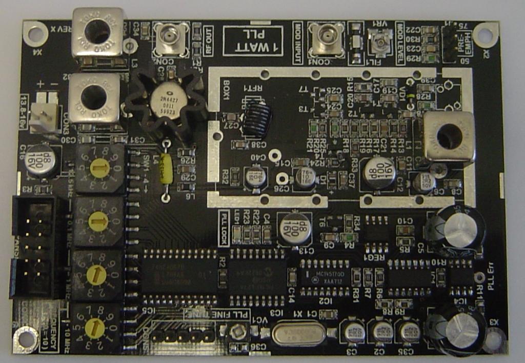
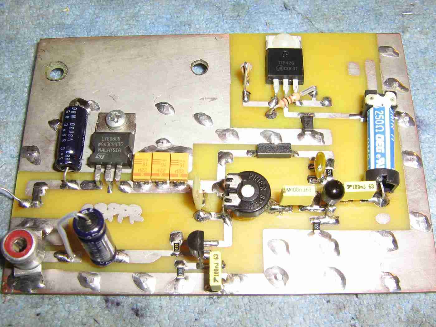
Overview of the Broadcast Warehouse PLL+ 1 Watt FM Exciter module.
Broadcast Warehouse's designs have surprisingly high-quality for being hobby kits. They incorporate a number of features found only on high-end broadcast exciters, including excellent audio response and rejection of spurious RF emissions which tend to be found on other designs.
The modulation input is via the solder pads on the lower-left. There was a RCA jack there originally but I removed it. The exciter has a jumper setting for 75 µS, 50 µS, or no pre-emphasis. No audio pre-emphasis will be used here as the input limiter discussed later will take care of that.
Next to the modulation input is the modulation adjust potentiometer VR1. This will need to be adjusted to give a 100% modulation level, which is a maximum deviation of +/- 75 kHz.
The RF output is via the bottom-center solder pads. There was also a RCA jack there originally, but I replaced with a direct coax connection going to a panel-mounted SMA jack.
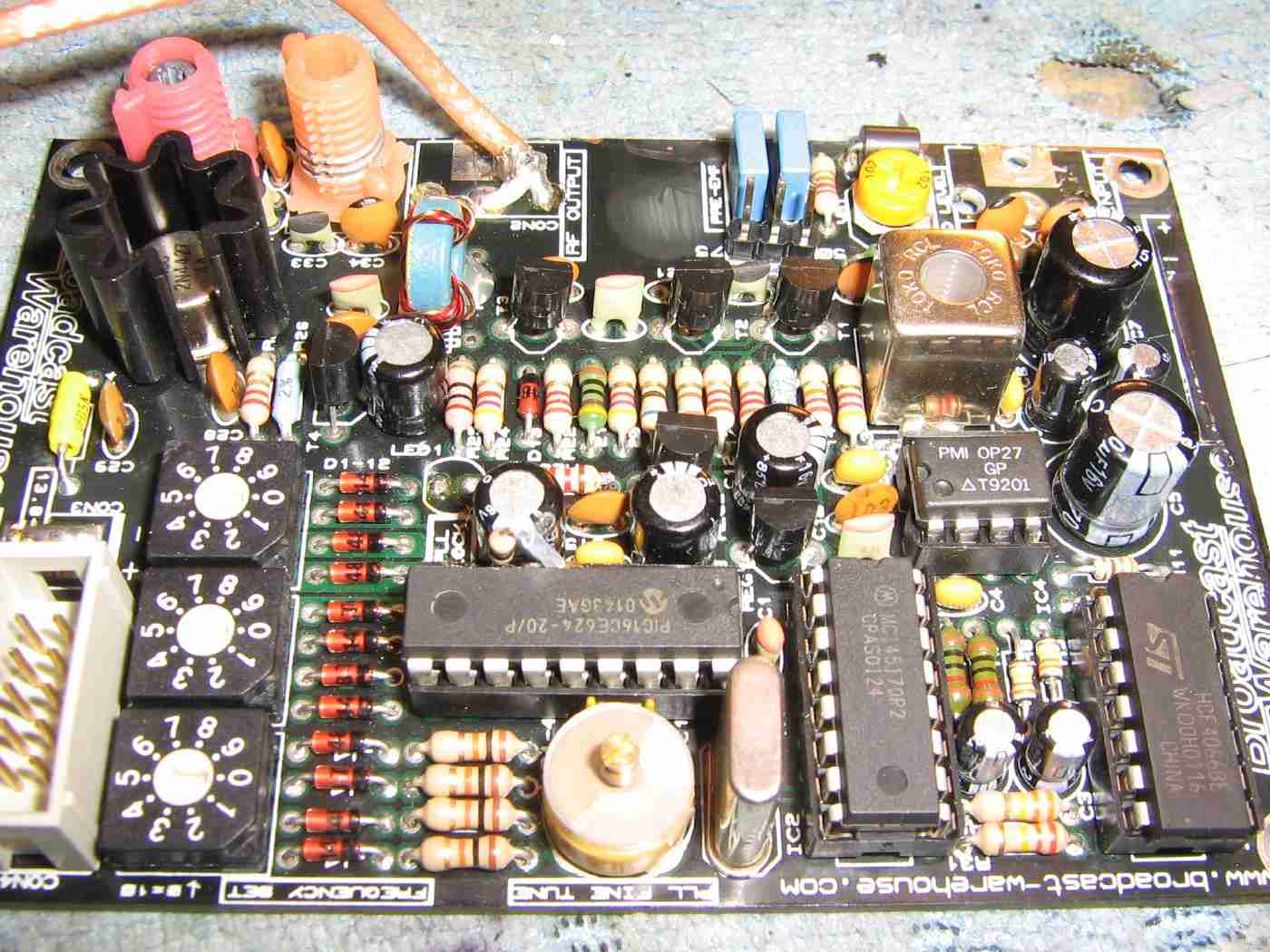
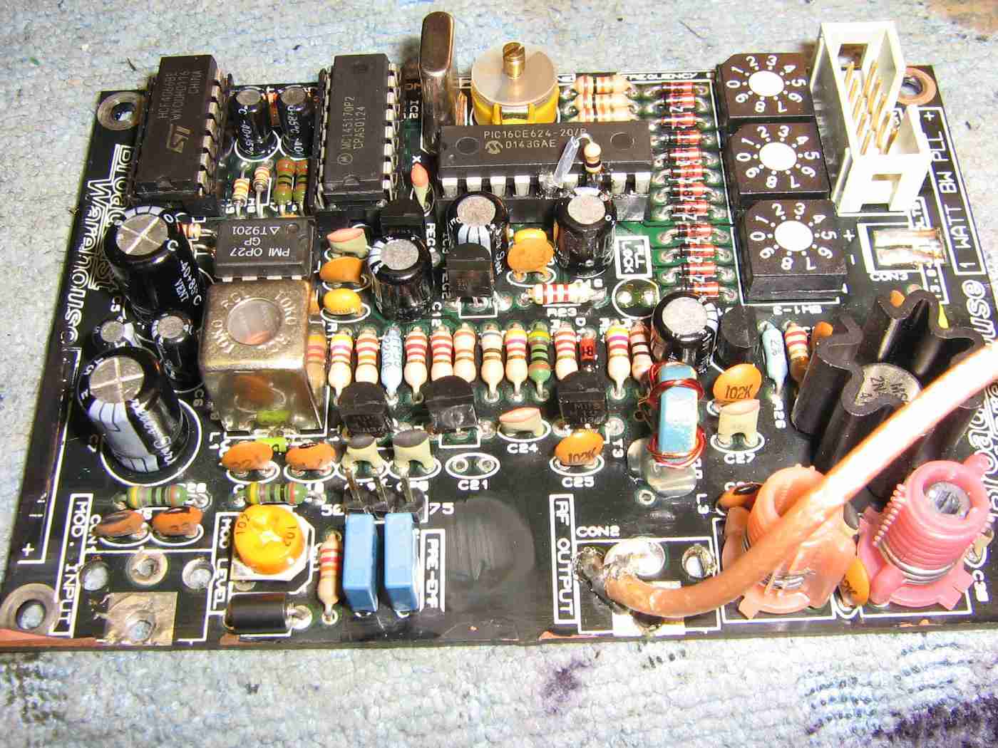
Alternate view.
The exciter module requires +12 to +16 VDC at around 300 mA. The RF output power is around 1 watt (+30 dBm) over the entire FM broadcast band (87.5 - 108 MHz in 100 kHz steps).
The yellow trimmer capacitor (bottom-center) can be used to tweak the final output frequency.
There is also a LED which lights when the PLL is locked. This PLL lock/unlock indicator LED should be panel-mounted.
I also replaced the stock LF351 PLL loop filter op-amp with a lower-noise OP27.
A dab of hot glue should be used to prevent RFT1 (the blue/yellow ferrite torroid) from flopping around.
The output frequency is selected by three DIP switches or by an external panel with a LCD display. The LCD control panel option will be covered here. You'll need to set the DIP switches to "555" if you are using the external LCD panel frequency control.
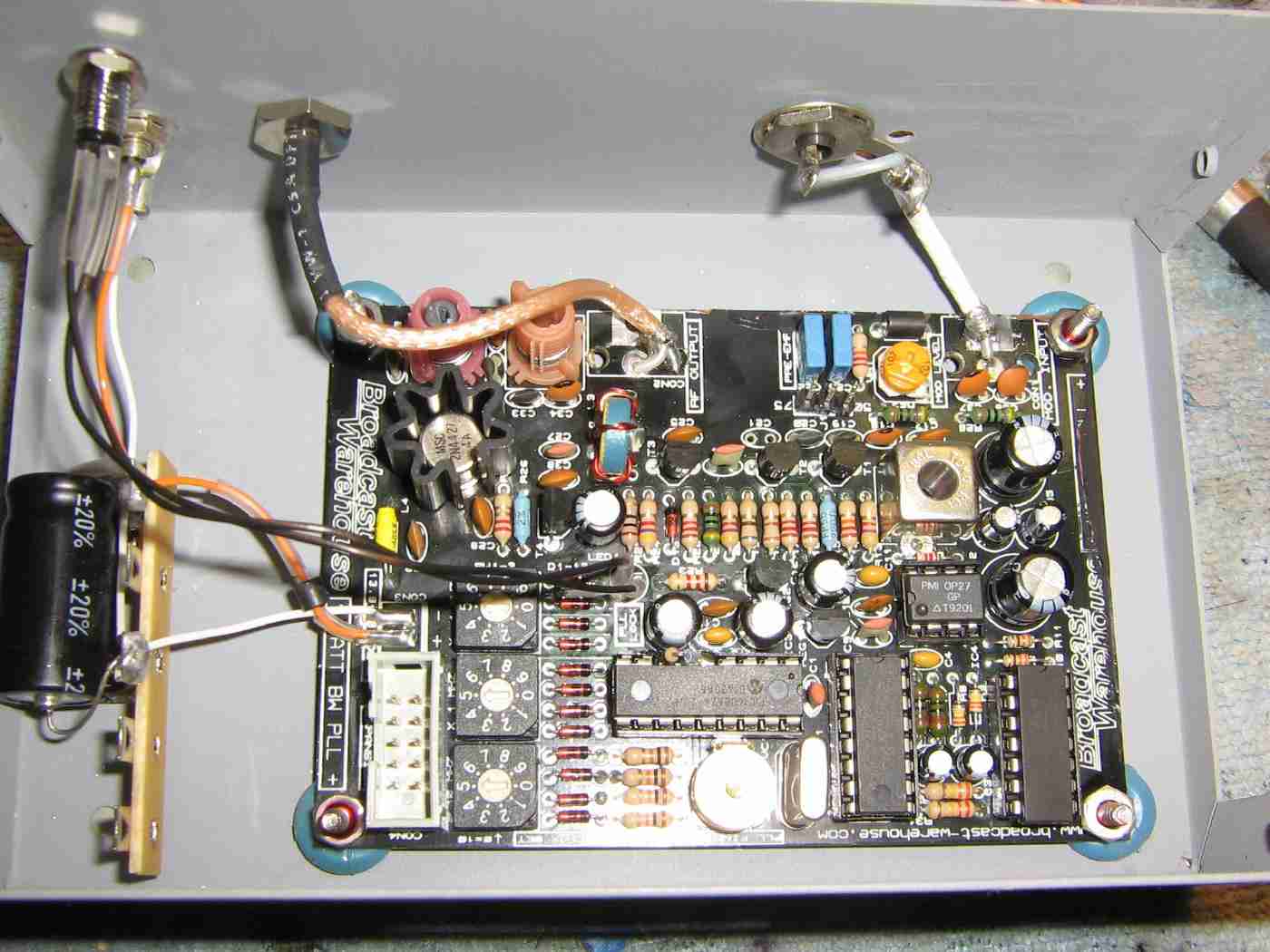
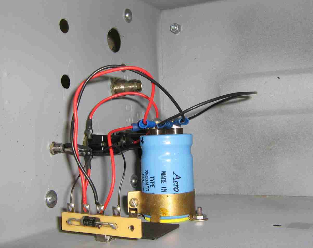
Mounting the exciter inside an old printer switch case.
DC power input is via the orange/white wires on the left. They first go to a terminal strip where a 470 µF capacitor helps to condition the input DC power.
Above the DC power input is the panel-mounted PLL lock LED.
Next to that is a panel-mounted SMA jack for the RF output.
On the right is a panel-mounted RCA jack for the modulation input, which will be coming from the stereo encoder/limiter in this case. It's possible to run "line level" audio directly into the exciter module, but the use of a pre-processing limiter/compressor is HIGHLY recommended.
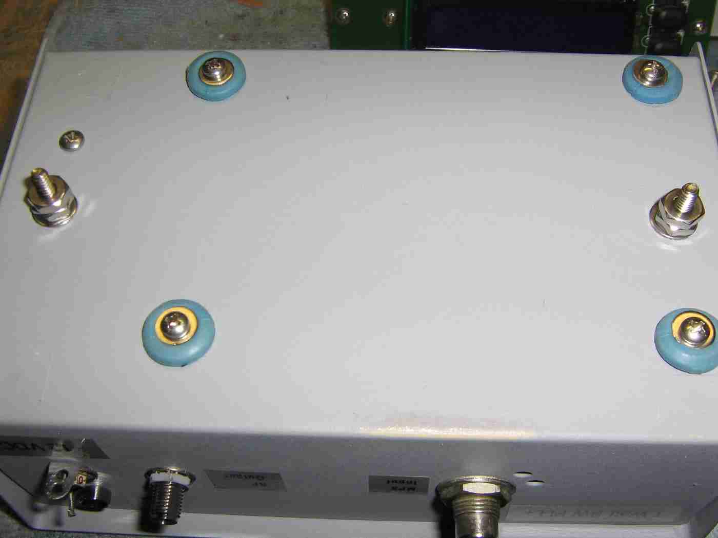
Because the exciter is vulnerable to microphonics induced by vibrations, the board itself will be mounted on four rubber grommets sandwiched using #4 stainless steel hardware.
The two #8 screws coming out of the bottom of the printer switch box will hold the case to the side of the ammo can it will be mounted in.
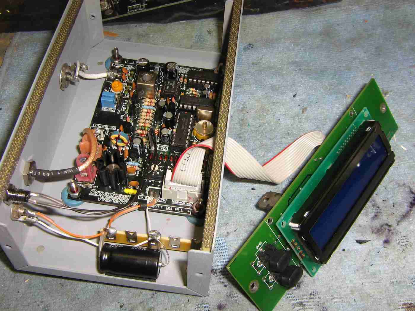
Connecting the external frequency control and LCD display panel to the exciter module.
The LCD display board also comes as a kit (or pre-built module) and with a short ribbon cable.
The two buttons toggle the frequency up or down between 87.5 MHz and 108 MHz.
The LCD displays the final choosen frequency and the words <UNLOCKED> when the PLL is unlocked and <LOCKED> when the PLL is locked.
The exciter powers down its final RF stage when the PLL is unlocked to prevent spurious RF emissions.
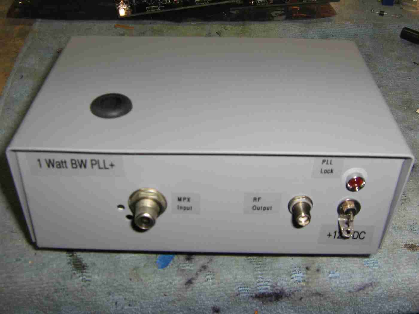
Finished exciter case external overview.
A hole was drilled in the top cover to allow access to the VR1 modulation adjustment potentiometer.
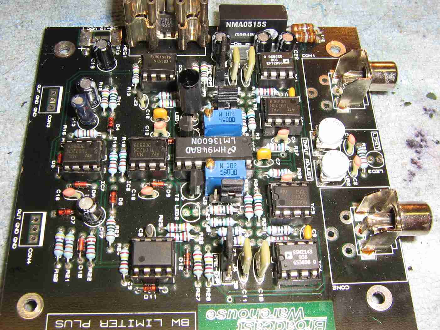
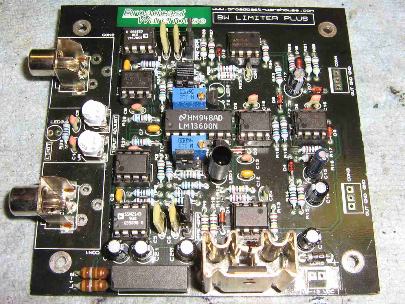
Overview of the Broadcast Warehouse Limiter PLUS.
The limiter requires +12 to +16 VDC with a minimal current draw.
The Broadcast Warehouse Limiter PLUS takes any audio input between -10 dBu and +18 dBu and either increases or decreases its level so it won't overmodule the exciter.
The limiter is stereo, so it has two audio inputs: left & right. It will also work in mono, if so desired.
There is also an onboard selectable "clipper" circuit. This can be enabled to artificially increase the "loudness" of your audio by clipping the peaks. This is what commercial radio stations do, but it tends to fatigue the ear of the listener.
Alternate view
The limiter has a jumper setting for 75 µS, 50 µS, or no pre-emphasis. The 75 µS pre-emphasis setting will be used here. The pre-emphasis settings tend to vary around the world.
The limiter has either unbalanced or balanced input/output connections. The unbalanced settings will be used here. Most "pro-level" audio gear uses balanced audio connections, while consumer-grade equipment is unbalanced.
Capacitors C5/C10 (6800 pF) and C6/C11 (4700 pF) help set the pre-emphasis time constant. These should be replaced with their polystyrene equivalent.
The "Limit" LED (labeled LED3) should be panel-mounted. Set the limiter's input audio level level so this LED flickers a bit.
The two other LEDs (labeled LED1 & LED2) should be painted black, or at least well shielded. These LEDs act as "hard limiters" in the clipping circuit and stray light modulation striking these LEDs can be induced onto the passing audio.
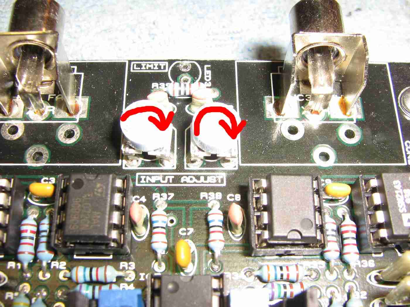
The two limiter audio input adjustment potentiometers (labeled VR1 & VR2) should be set full clockwise.
The Broadcast Warehouse Limiter PLUS will handle just about anything, so let it do its job. Use an external audio mixer to control the audio levels into the limiter, if so desired.
The first step in setting up the limiter after it has been built is to trim any voltage offsets in the op-amps. This will reduce the overall distortion in the rest of the system. Apply DC power (+12 VDC) to the limiter without any audio and follow these steps:
Connect a multimeter to the output of the left channel and set the meter onto a millivolt DC range. Now adjust the multiturn potentiometer VR4 for the minimum output voltage on the meter. Aim for a reading of a few millivolts or less. Repeat the procedure for the right channel with VR3.
Decide on the pre-emphasis settings for your country / region. 75 µS for the Americas and Japan and 50 µS for the rest of the world, usually. Set the pre-emphasis with the jumpers.
Make sure to remove the pre-emphasis on the stereo encoder and exciter.
Decide on "Clarity" or "Loud" modes. Clarity will produce a closer to the original sound while loud will give you a more processed commercial sound. Set the jumpers to your chosen mode.
Apply audio to the inputs of the limiter and adjust the the input gain controls to maximum (clockwise). You should have the LED limit indicator flashing with the peaks of the audio, if not, then you need to apply more audio level from your audio source. When the limiter is limiting (LED is flickering) then you can adjust your transmitter's modulation control for a peak deviation of +/- 75 kHz.
You may wish to readjust the input gain controls on the limiter so that the limiter starts to limit at your desired input level, or you can leave the input level controls at maximum to get the limiter to act more as a compressor and increase your average volume.
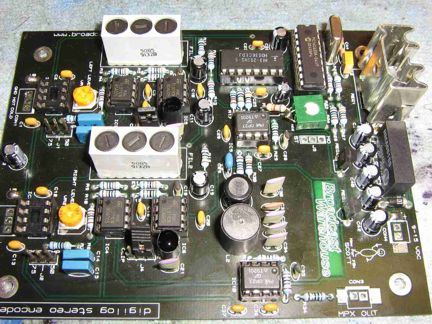
Overview of the Broadcast Warehouse DIGILOG Stereo Encoder.
The stereo encoder requires +12 to +16 VDC with a minimal current draw.
FM broadcast stereo encoders are designed take the two left and right channels and combine them into "Left + Right" and "Left - Right" components. The "Left + Right" spectrum occupies everything below 15 kHz to provide for monaural receivers. The "Left - Right" component is converted into a double-sideband suppressed signal at 38 kHz. This modulation creates a upper- and lower-sideband centered around a 38 kHz (supprressed) carrier.
The stereo encoder also generate a 19 kHz pilot tone signal. This pilot tone is used to indicate a stereo signal is present at the receiver and the receiver also doubles this 19 kHz signal to help demodulate the "Left - Right" sideband. The receiver then reverses the process, converting the "Left + Right" and "Left - Right" signals back into the individual left and right audio channels.
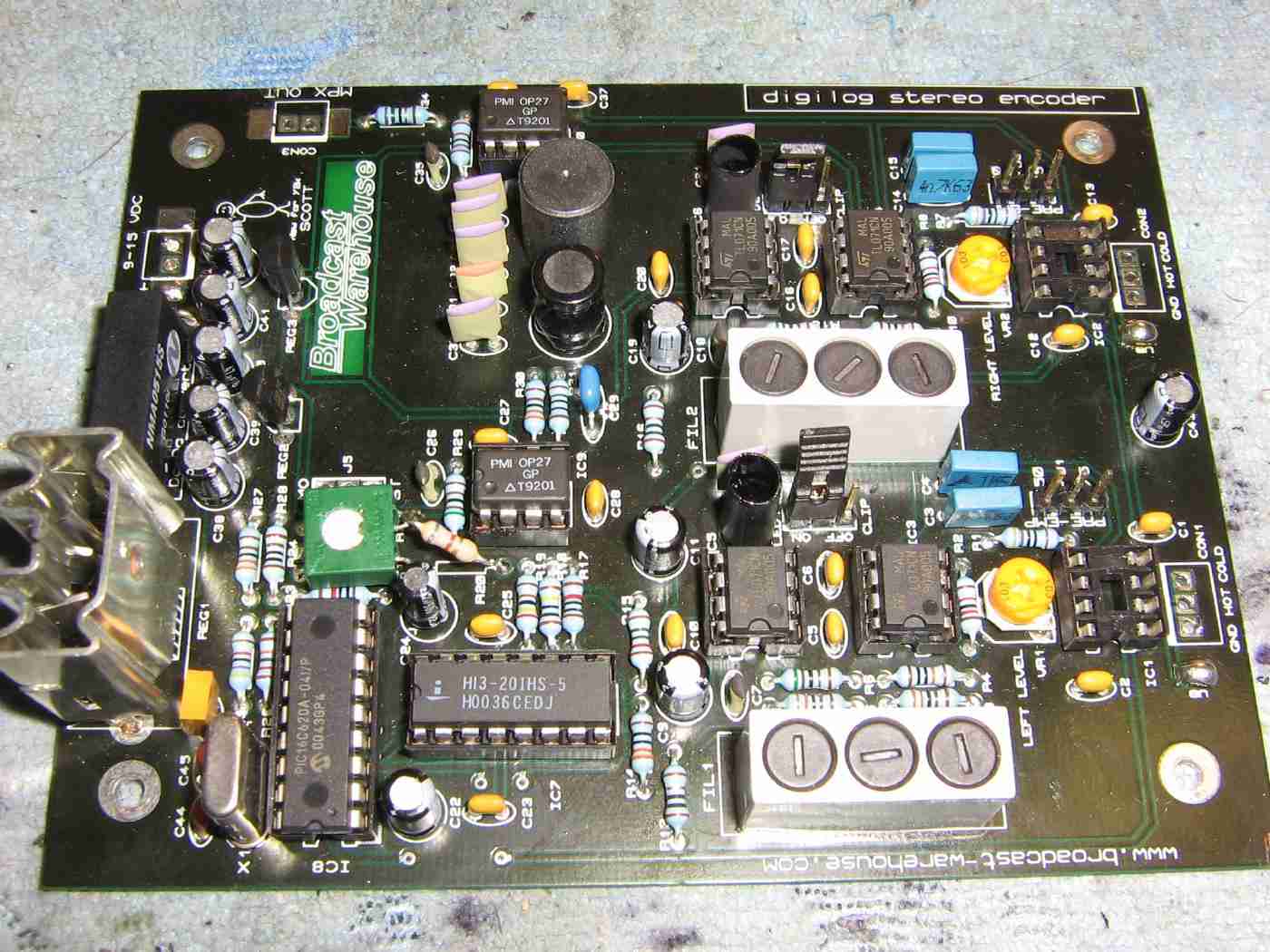
Jumper J5 selects either "Stereo" or "Mono" mode. You should change this out to a panel-mounted switch. It's handy to quickly switch between stereo or mono for certain low-power FM applications. Mono tends to work better in the fringes, which is just about everywhere when dealing with low-power FM.
The stereo encoder should also have its pre-emphasis settings disabled.
The "clip" jumpers should be set. This is to clip anything which may have gotten past the limiter.
The clipping LEDs should also be painted black or shielded, just like the limiter.
IC9 and IC10 were replaced with OP27 low-noise op-amps.
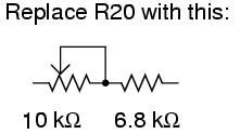
The stereo encoder has a fixed 9% modulation for the 19 kHz pilot tone, but you can tweak it a bit by replacing resistor R20 (13 kohm) with a 10 kohm potentiometer in series with a 6.8 kohm resistor on its wiper.
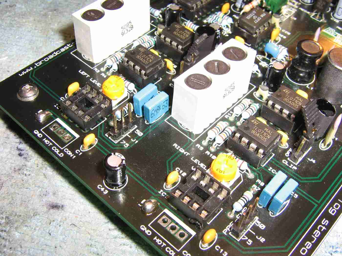
For unbalanced audio inputs to the stereo encoder, apply the audio via the "COLD" and "GND" solder pads. You should also apply a solder jumper to the exposed "UB" solder pad next to the audio inputs.
Potentiometers VR1 and VR2 will be used for setting the main left and right audio levels.
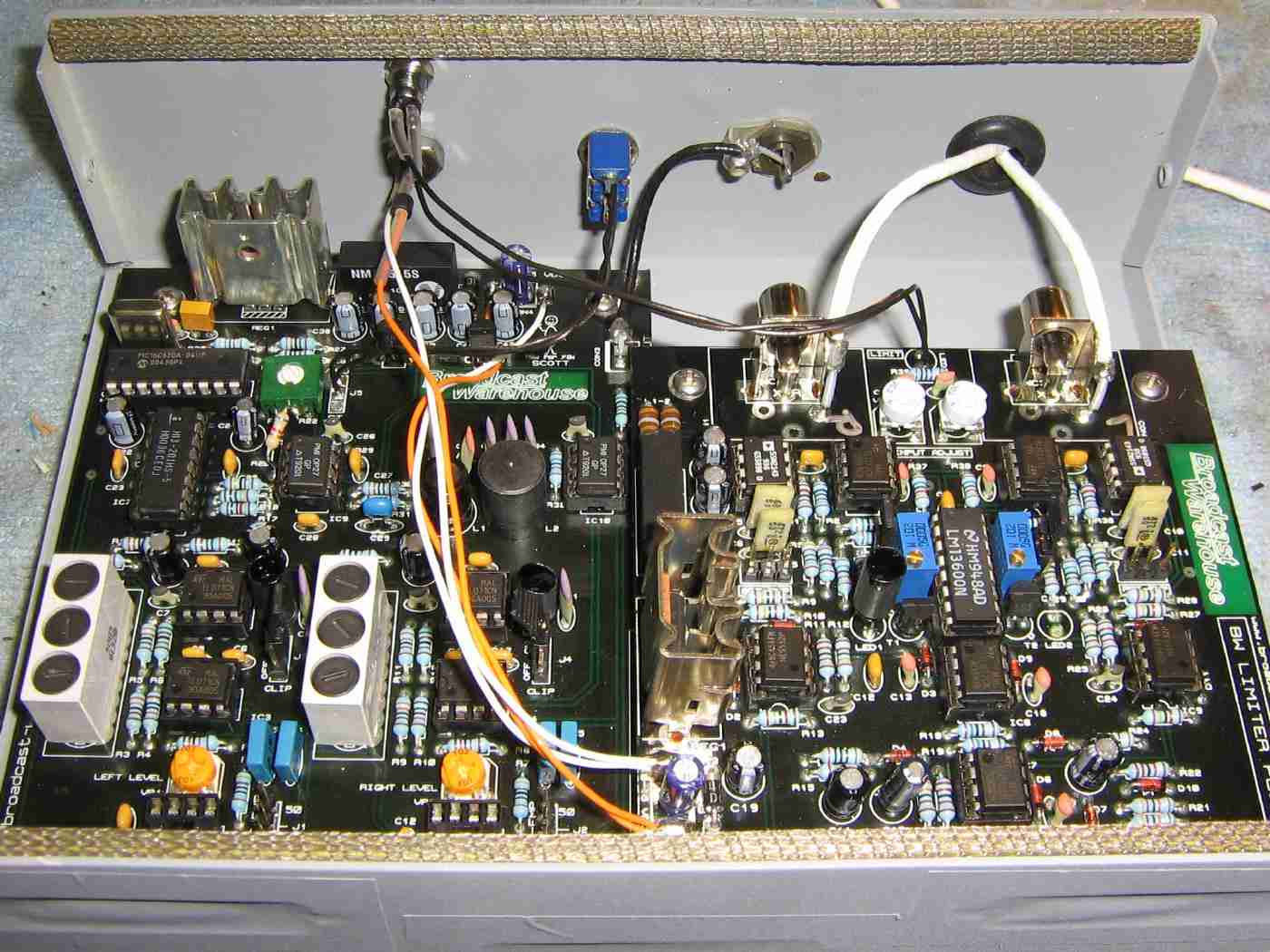
Mounting the Broadcast Warehouse Limiter PLUS and Broadcast Warehouse DIGILOG Stereo Encoder in a large printer switch case.
On the right-side, the left and right audio inputs are via two pieces of white coaxial cable.
To the left of those coax cables is a panel-mounted RCA jack for the output signal from the stereo encoder. This connects to the exciter's modulation input.
To the left of that RCA jack is a panel-mounted switch to select between stereo and mono. Just solder wires from the J5 solder pads to directly to the switch.
A panel-mounted LED for the limiting indicator and a feed-through capacitor for the DC input power are on the left-side.
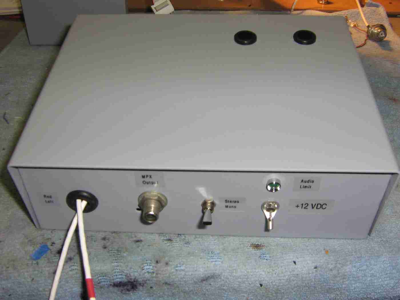
Finished limiter / stereo encoder case overview.
The two holes in the cover are for access to the audio level input controls on the stereo encoder.
The modules will be housed inside an old ammo can.
Regulated +12 VDC input is via banana jacks along the bottom.
A SPST switch controls the main DC power.
A 2 amp fuse and 1N5401 shunt diode protect against voltage polarity reversal.
An optional 10,000 µF capacitor was added to filter any residual ripple on the DC input.
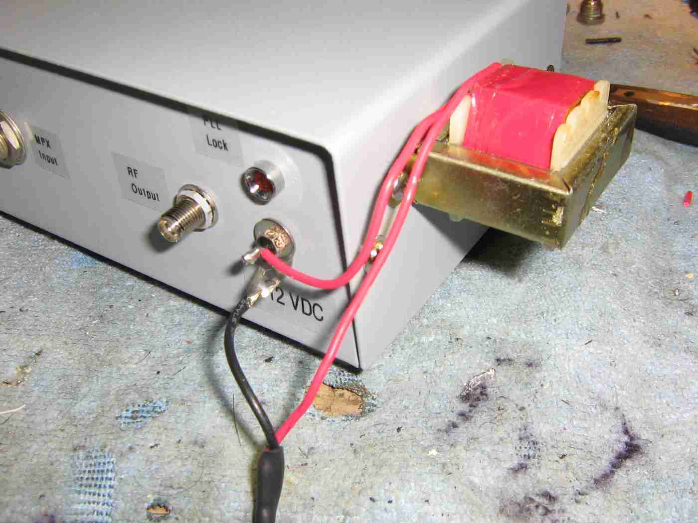
Another option is adding a 1 henry inductor in series with the DC power lines. These inductors are very useful for cleaning up any "hash" when powering the transmitter from a vehicle's DC power system.
Ideally, a single large filter inductor should have been mounted in series with the main DC input, right before the ripple capacitor.
You can find these large inductors in surplus mobile-mount CB radios.
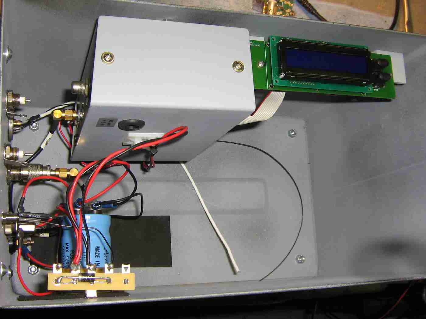
Mounting the exciter case and the LCD display.
The LCD display is mounted on two little aluminum L-brackets.
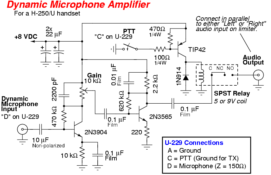
This is an optional microphone amplifier and PTT control circuit board.
It's designed for use with a surplus Sonetronics H-250/U noise cancelling military handset.
The handset's PTT switch controls a relay which applies the microphone audio to one of the channels on the limiter's audio input.
This is useful for emergency situations where you may need to notify a large number of people quickly via radio, or for calling in bomb strikes.
It's also useful for when you tune all the FM radios at Best Buy to the same frequency and then transmit rude comments over the air...
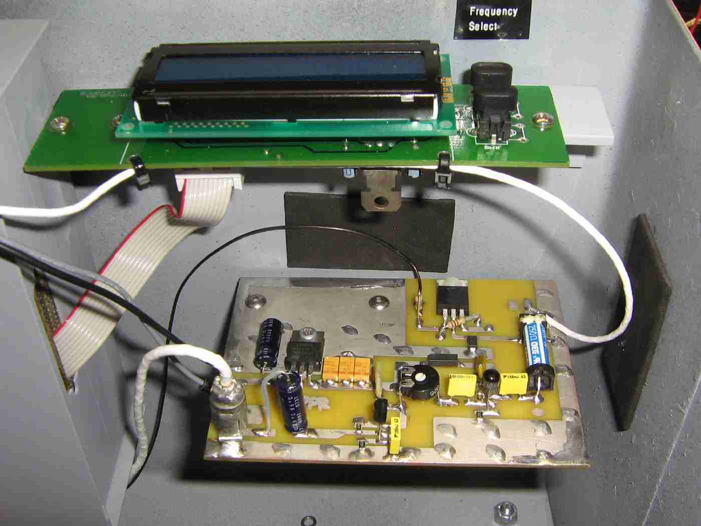
Mounting the microphone amplifier and control circuit board just below the LCD display.
The microphone audio input from the H-250/U handset is via the RCA jack along the lower-left.
The amplified microphone audio is then sent to the "Left" channel on the limiter via the coax cable after the relay on the right.
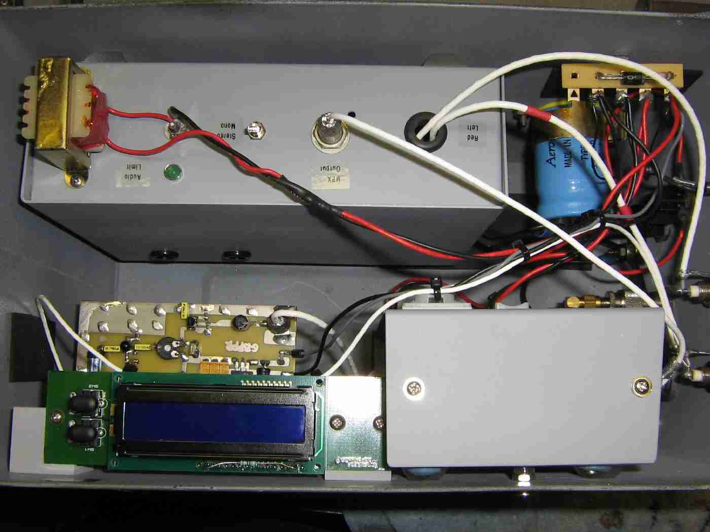
Mounting the audio limiter / stereo encoder case.
Be sure to use shielded wire or coax on all the audio connections.
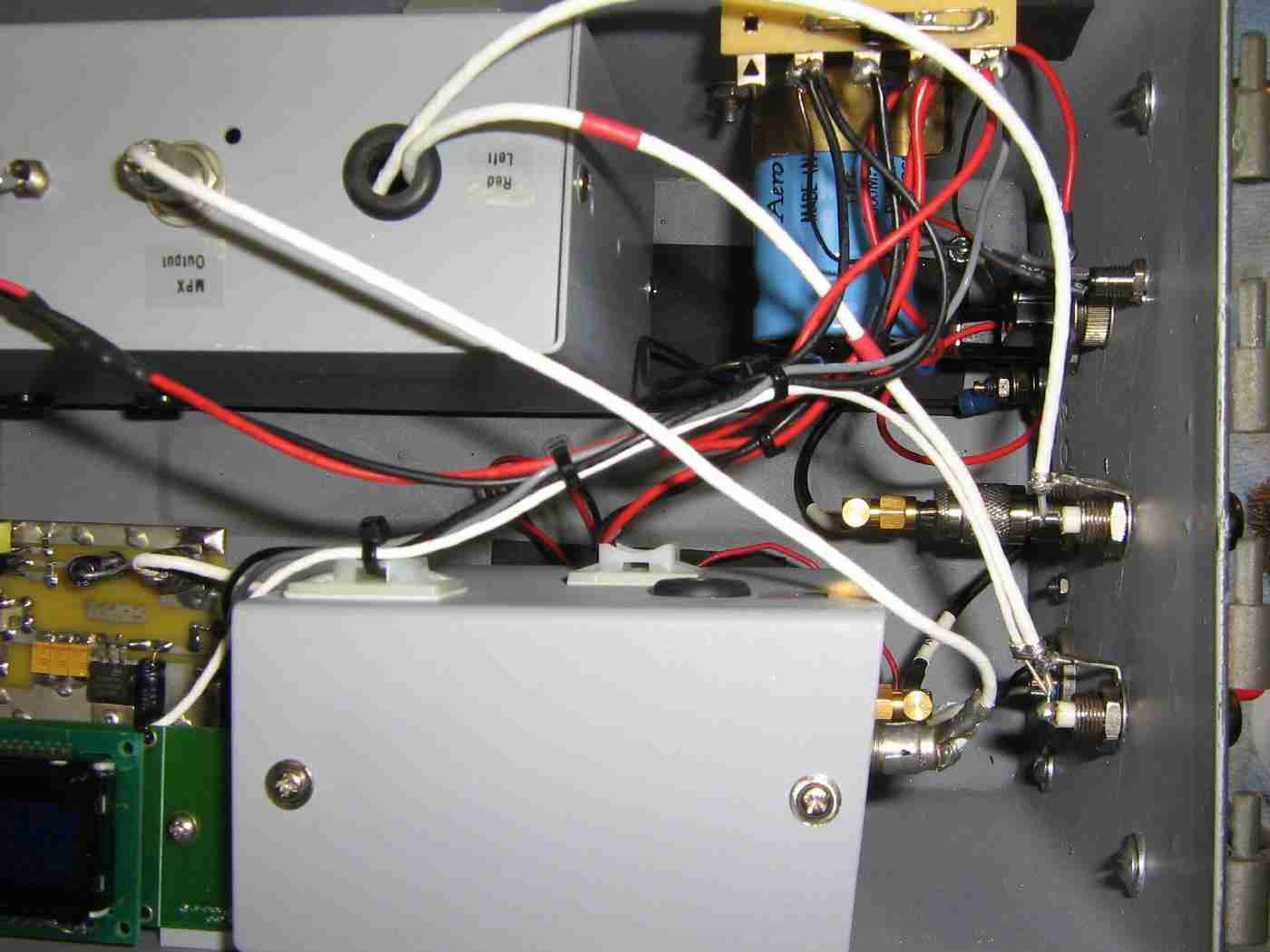
Behind the front-panel overview of the fininshed low-power FM broadcast transmitter.
Audio inputs (left and right) are via the BNC jacks on the top.
RF output is via a SMA-to-TNC adapter to a panel-mounted TNC jack.
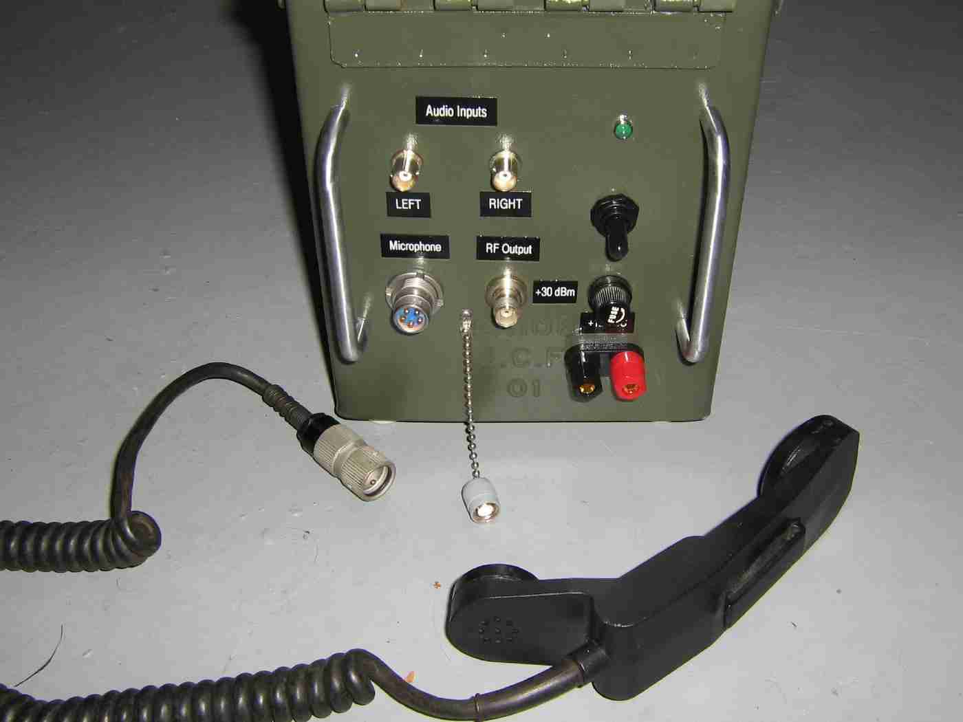
Front-panel overview of the fininshed low-power FM broadcast transmitter.
The U-229 connector for the H-250/U handset is on the bottom-left. On the bottom-center is the TNC jack for the RF output.
The two BNC jacks along the top are for the audio input.
Main DC input is via the banana jacks on the lower-right.
Avoid mounting the LCD display externally to keep the transmitter unit fairly weather resistant.