This is my version of the analog-to-digital converter for Scotty Sprowls' Modularized Spectrum Analyzer (MSA) project. The original analog-to-digital converter design is SLIM-ADC-16.
The spectrum analyzer's Analog-to-Digital Converter (ADC) stage is based around (two) 16-bit Analog Devices AD7685 serial ADCs There is no need for any external (manual) reference adjustment to set the ADC conversion range and it'll still obtain excellent resolution in the MSA/VNA systems. Each ADC will digitize its input of 0 to 5 volts into a binary serial stream equal to 0 to 65,535. This equates to approximately 76.3 µV per bit resolution. Only one AD7685 will be used in this spectrum analyzer design. The second AD7685 for the VNA phase detector will be constructed and discussed in a future article.
The "MAGVOLTS" magnitude output from the logarithmic detector is connected to the ADC's input. This voltage range should be from +0.4 volts to +2.4 volts (over the AD8306's 100 dB range). The AD7685 will then convert +0.4 volts to a bit value of 5,243. The +2.4 volts will convert to a bit value of 31,457. The overall dynamic bit range is equal to 26,214 bits (31,457 - 5,243). Therefore, the conversion factor for the MSA's combination of logarithmic detector and 16-bit ADC is: 100 dB / 26,214 bits = 0.0038 dB per bit resolution. This is what determines the final displayed RF power magnitude on the spectrum analyzer.
Both ADCs will capture and clock-out their data simultaineously. The MSA software commands both ADCs to begin conversion with a single toggle of the CONVERT line. 16 toggles of the SERCLOCK line causes the AD7685 to output a serial stream of 16 bits. The Serial Data Output (SDO) of the AD7685 (pin 7) has a limited current (500 µA) capability. Therefore, a 2N2222A transistor provides buffering and current sinking to drive the WAIT and ACK lines on the controlling computer's parallel port (LPT). The computer's LPT port is normally a TTL-compatible input with an internal pull-up resistor to +5V. Having two pull-up resistors shouldn't hurt and should help make the circuit compatible with different computers. You may have to experiment with different BIOS settings for your computer's parallel port if you encounter problems.
To control the AD7685, two main control lines are used: CONVERT and SERCLOCK. Both AD7685 chips are controlled simultaneously. Before conversion, these lines are held low. To begin conversion, the CONVERT line is commanded high. This initiates the AD7685's in-chip sample-and-hold circuit. While CONVERT is high, any voltage changes on the analog input(s) will be disregarded. Also, the SDO output will be high impedance (WAIT and ACK will be high impedance).
It takes approximately 2 µS for the 16-bit conversion (sample) to take place. When complete, the 16-bit data word will be stored in the AD7685's buffer (hold). After conversion is complete, the CONVERT signal is brought low. The Most Significant Bit (MSB) D15 will be present on the SDO pin (there is a logic inversion by the 2N2222A on the line back to the computer, WAIT or ACK). Each time the SERCLOCK is brought low, the data word is shifted by one bit.
The data is valid 15 nanoseconds after the negative edge of SERCLOCK. It takes sixteen SERCLOCKs to shift out the 16-bit data word. If no data is clocked out of the buffer, the next CONVERT signal will overwrite the buffer.
MSA Software
The MSA software works in this way:
1.) It begins with CONVERT and SERCLOCK lines held low.
2.) CONVERT to high. This initiates the A-to-D conversion process.
3.) CONVERT to low. High-to-low takes about 5 µS, allowing the minimum 2 µS conversion time requirement.
4.) SERCLOCK to high. D15 MSB is valid on SDO, and is read by the computer.
5.) SERCLOCK to low. Next data word bit is shifted.
6.) SERCLOCK to high. D14 bit is valid on SDO, and is read by the computer.
7.) SERCLOCK to low. Next data word bit is shifted.
8.) SERCLOCK to high. D13 bit is valid on SDO, and is read by the computer.
9.) SERCLOCK to low. Next data word bit is shifted.
10.) SERCLOCK to high. D12 bit is valid on SDO, and is read by the computer.
11.) SERCLOCK to low. Next data word bit is shifted.
12.) SERCLOCK to high. D11 bit is valid on SDO, and is read by the computer.
13.) SERCLOCK to low. Next data word bit is shifted.
14.) SERCLOCK to high. D10 bit is valid on SDO, and is read by the computer.
15.) SERCLOCK to low. Next data word bit is shifted.
16.) SERCLOCK to high. D9 bit is valid on SDO, and is read by the computer.
17.) SERCLOCK to low. Next data word bit is shifted.
18.) SERCLOCK to high. D8 bit is valid on SDO, and is read by the computer.
19.) SERCLOCK to low. Next data word bit is shifted.
20.) SERCLOCK to high. D7 bit is valid on SDO, and is read by the computer.
21.) SERCLOCK to low. Next data word bit is shifted.
22.) SERCLOCK to high. D6 bit is valid on SDO, and is read by the computer.
23.) SERCLOCK to low. Next data word bit is shifted.
24.) SERCLOCK to high. D5 bit is valid on SDO, and is read by the computer.
25.) SERCLOCK to low. Next data word bit is shifted.
26.) SERCLOCK to high. D4 bit is valid on SDO, and is read by the computer.
27.) SERCLOCK to low. Next data word bit is shifted.
28.) SERCLOCK to high. D3 bit is valid on SDO, and is read by the computer.
29.) SERCLOCK to low. Next data word bit is shifted.
30.) SERCLOCK to high. D2 bit is valid on SDO, and is read by the computer.
31.) SERCLOCK to low. Next data word bit is shifted.
32.) SERCLOCK to high. D1 bit is valid on SDO, and is read by the computer.
33.) SERCLOCK to low. Next data word bit is shifted.
34.) SERCLOCK to high. D0 bit is valid on SDO, and is read by the computer.
35.) SERCLOCK to low. SDO is high impedance.
36.) Subsequent SERCLOCKs do nothing and the conversion process repeats.
Video Filter
This magnitude ADC circuit is designed with an optional input video bandwidth filter based around an Analog Devices ADG704 4-channel multiplexer. This will allow a selection of additional capacitance to be placed in parallel with the AD7685's input.
The ADG704 can be used to select four different integration times (video bandwidths) for the final displayed magnitude signal. The capacitor values for the video filter were chosen arbitrarily and you may wish to experiment with different values.
The video filter helps to remove excessive noise before the analog-to-digital conversion process and is a simple way to "narrow" to the response of the spectrum analyzer.
The MSA software video filter selections:
V0    V1       Filter Selection     Video Bandwidth
0     0        S1 - 1000 pF         Wide
0     1        S2 - 0.01 µF         Medium
1     0        S3 - 0.1 µF          Narrow
1     1        S4 - 1.0 µF          Extra Narrow
Scotty's software video filter controls may still be experimental at this point.
The video bandwidth determines the spectrum analyzer's capability to discriminate between two different power levels. This is because a narrower video bandwidth will remove noise in the logarithmic detector output. This filter is used to "smooth" the final display by removing any noise from the signal envelope.
(wikipedia.org/wiki/Spectrum_analyzer#Video_bandwidth)
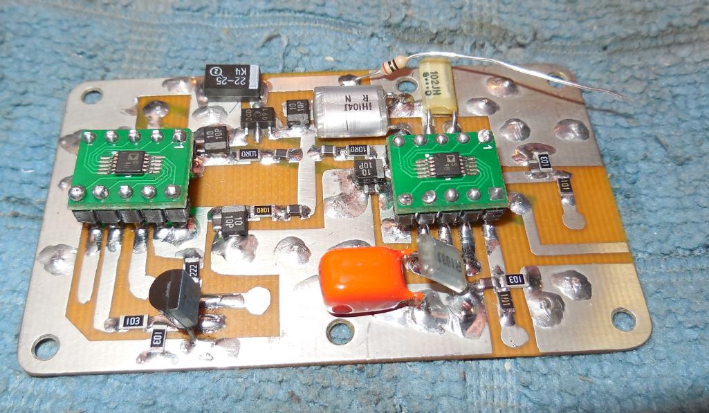
Overview of the ADG704 video filter (right) and AD7685 16-bit ADC (left).
Both the AD7685 and the ADG704 are in 10-pin MSOP packages, so MSOP-to-DIP converters were used for soldering convenience.
Polystyrene capacitors are used in the video filter section and the large non-polarized orange capacitor (1 µF) is for the "extra narrow" video filter selection.
The 2N2222A transistor buffer is on the lower-left.
The SOT-89 device is a Sieko S-81250SG precision 5 volt regulator.
The "reference" voltage (pin 1) for the AD7685 should be very well filtered and regulated for maximum performance and magnitude resolution.
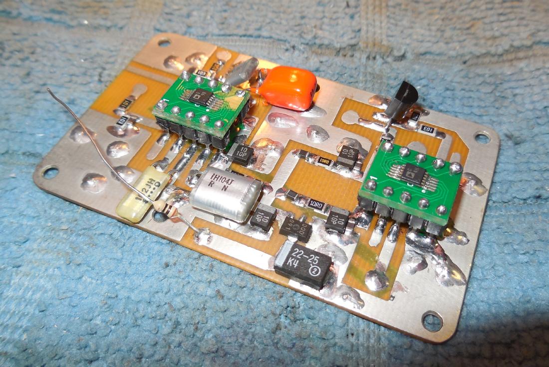
Alternate view.
The capacitors for the video filters should be low-leakage, non-microphonic, high-quality film types (polystyrene, Teflon, etc.). Otherwise, switching in the video filters could cause a small shift in the magnitude voltage.
The selectable video bandwidths are somewhat arbitrary. The wide video bandwidth is for the highest sweeping speed, medium for general speed, and narrow for very slow sweeping or to get the most accurate magnitude/phase data.
The ADG704 video filter is optional and if not used, a single 1000 pF capacitor should be added across the input (pin 3) of the AD7685.
This corresponds to a "wide" video filter as you do want a little bit of low-pass filtering here to keep the noise out, but not too much.
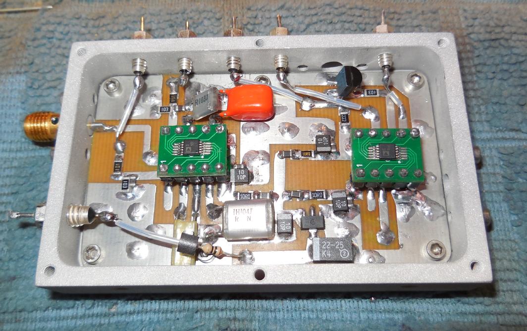
Completed overview of the analog-to-digital converter with video filter.
It's mounted inside an old 800 MHz cellular phone receive pre-amplifier case.
The SMA jack on the left is used for the MAGVOLTS input.
A 1000 pF feed-through capacitor (lower-left) is used for the +12 VDC power input.
180 pF feed-through capacitors are used for the ADG704 and AD7685 control lines. These should be low-value capacitors to avoid distorting the control waveforms.
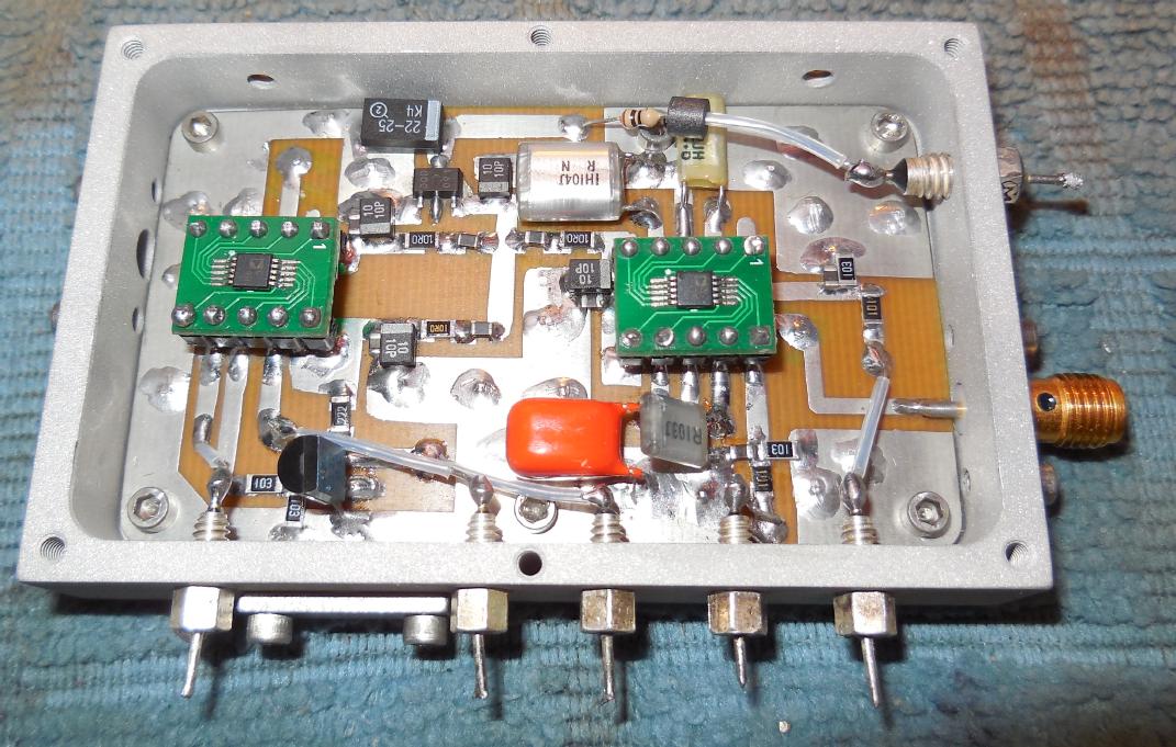
Alternate overview.
AD7685 voltage conversions:
Analog Input (Volts)            Digital Output (Hexadecimal - Binary)
4.999924                        FFFF    1111111111111111
2.500076                        8001    1000000000000001
2.500000                        8000    1000000000000000
2.499924                        7FFF    0111111111111111
0.000076                        0001    0000000000000001
0.000000                        0000    0000000000000000

0.400000                        147B    0001010001111011
2.400000                        7AE1    0111101011100001
The two Least Significant Bits (LSB) are somewhat noisy which yields a more realistic 14-bit resolution. Therefore, with this circuit, the magnitude resolution of the MSA is actually around 0.01 dB.
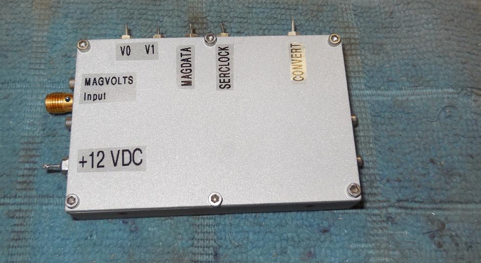
Finished case overview.
The MAGVOLTS input of this module will then be connected back to the Logarithmic Detector stage. Be sure to use coaxial cable for this connection.
The CONVERT, SERCLOCK, MAGDATA, V0, and V1 lines go back to their respective latches on the Control Board.
CONVERT goes to latch P3D7.
SERCLOCK goes to latch P3D6.
MAGDATA goes to WAIT (DB25 pin 11).
V0 goes to latch P4D0.
V1 goes to latch P4D1.


