SPECTRUM ANALYZER/MONITOR RECEIVER
AND TRACKING GENERATOR
SCIENCE
WORKSHOP
Home of the "Poor Man's
Spectrum Analyzer"
P.O.
Box
528
Medford , NY 11763
Email: radioguy@hoflink.com
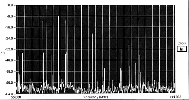
*Display the RF Spectrum from 2 to
2,150MHz, and act as a continuous-tuning AM/FM receiver. *Measure the amplitude
and frequency of RFI generated by your computer or electrical appliances, and
instantly evaluate the results of
filtering or shielding.
( Photo
supplied by Marty, KG6FOQ )
*Examine Satellite TV signals and their sub-carriers. (Curious about those "secret" signals ?)
*Identify modulation modes such as AM, FM, SSB, FSK, PCM etc. *Sweep an area for illegal "bugs".
*Signal trace transmitters and receivers, check "gain-per-stage" when building or troubleshooting and test for harmonic or intermodulation distortion.
*Check your transmitter output for "spurs". *Receive "on-carrier" or "sub-carrier" ATV sound.
*See if the band is "open" at a glance, or find a quiet spot on the band.
*Monitor ALL the local repeaters SIMULTANEOUSLY! *Make field strength measurements.
*Orient and tune antennas (and antenna tuners) for maximum results across a band of frequencies.
*Tune antenna duplexers or diplexers, make VSWR measurements, measure insertion loss and tune RF filters.
These are only a few of the applications for the New Science Workshop Spectrum Analyzer/Receiver. With "RF-Vision" you will have a new monitoring mode, with rapid signal detection, modulation analysis and band condition and activity information constantly available at your finger tips! Through it’s many applications, this new instrument provides information and operating techniques not available in any other way.
A short tutorial in PDF format.
SOME HISTORY.
Back in 1978, I assembled a few pieces of surplus electronic gear into what I affectionately called "The Poor Man’s Spectrum Analyzer". I demonstrated it at the Dayton Ham Fest, and sold out on the first day. One of the key items was a surplus TV IF strip which I had narrow-banded for this application. I found a few more, sold out again and then we were out of the Spectrum Analyzer business! The excitement created by this extremely low-cost approach to spectrum analysis and display inspired me to see if I could design a simple circuit that could do all that the original package did, and maybe a bit more.
Well, we’ve done it! The new
design is simpler, more stable, and has greater dynamic range. How could we do
all this and still come up with a package that meets the economical goal of
being called the "Poor Man's Spectrum Analyzer"? Simple. Careful
compromise! We would all love to have an instrument which would have all of the
features of the $30,000 machine or even settle for the features and accuracy of
the $5,000 machine. But we also realize that it’s not in the cards for under
$100. How about a machine that would do ALMOST everything the
professional models do, but one that would require a little more effort and
ingenuity on our part when it came to making precise measurements? Isn’t half a
loaf better than none? Many times it is- and I believe this is one of those
times. The original kit was based on these assumptions, and we made lots of
friends with it! The results - both in performance and educational value, are
impressive. Once you’ve had the opportunity to use it and appreciate it’s
potential, you will probably find applications that we haven’t even dreamed of!
HOW DOES IT WORK?
Basically, the "Poor Man’s Spectrum Analyzer" sweeps a voltage-tuned front-end over a range of frequencies in synchronism with the horizontal sweep of a scope. The received signal is passed through a narrow band filter and the detected signal is applied to the vertical amplifier of the scope. No signal, no vertical deflection. The deflection produced by the signal is proportional to the received signal’s strength. Resolution is approximately 250 KHz, which is determined by the bandwidth of the filter.

Since the output of the analyzer is audio, it can use ANY SCOPE for the display! If you don’t have one, pick up the cheapest "flea market special" that produces a horizontal line! The analyzer functions as a TUNABLE RF VOLTMETER with "eyes" and "ears". This makes it a natural for signal tracing receivers and transmitters, making relative gain-per-stage measurements, tuning transmitters, receivers, antennas and duplexers, locating and identifying sources of RFI, checking receiver local oscillator radiation, transmitter spurs, remote off-the-air repeater transmitter monitoring, etc. Using the analyzer on a transmitter, provides a display of the frequency, amplitude, and purity of the oscillator, frequency multiplier, and final signals. While a wattmeter indicates the total power output of a transmitter, the analyzer will tell you how much of that power is the desired output signal and how much of it is "garbage". Have you ever "peaked-up" on a spur? How would you know? Wouldn’t you like to see the level of the synthesizer sidebands? The harmonics? The high sensitivity of the instrument permits signal tracing receiver circuits from the antenna through the low-level RF stages. If the output of an RF amplifier stage contains signals not visible on the input, the RF stage is generating distortion products as a result of either overload, incorrect bias, etc. A conventional RF voltmeter (or scope) simply sums all of the voltages with no indication of the individual frequency components. Not so with the Spectrum Analyzer!
In addition, the analyzer displays
the presence of the local oscillator signal, as well as it’s frequency and
injection level. The Science Workshop "Poor Man’s Spectrum
Analyzer/Receiver" may not provide you with the built-in calibration
convenience of it’s bigger brothers, but it will provide you with a basic
instrument that will teach you how a Spectrum Analyzer works, do all the good
things we’ve described, provide you with a continuous tuning AM/FM, UHF/VHF
sound receiver and best of all- it’s price GUARANTEES NOT to make YOU a
"POOR MAN"!
HOW DO I START?
The "Poor Man’s Spectrum
Analyzer/Receiver has been designed and packaged as a semi-kit to provide the
cost-conscious Ham/Experimenter the opportunity to assemble his unit at the
lowest possible cost. The heart of the instrument is what we call the
"Main Board Assembly". It contains the converter, IF filter,
amplifier/detector and audio amplifier sections. All on a 3" X 4 l/2"
PC board. Adding the SW-5800 modified cable tuner gives us the Basic Spectrum
Analyzer, tuning from a few MHz up to approx. 500 MHz! Add additional tuners to
extend the freq. range.
WHAT ELSE DO I NEED?
A sawtooth horizontal sweep
voltage is required to deflect the beam horizontally across the screen of the
scope, and at the same time, cause the varactor tuner to scan across the RF
band. Many scopes provide access to the internal horizontal sawtooth voltage.
If your scope does, that’s all you need. Our instructions show you how to use
it. If your scope doesn’t, we’ve provided another kit to do the job. It also
provides a voltage regulator and the circuitry necessary to integrate the
controls for "width", "sweep rate" and "center frequency".
Makes it a lot easier to assemble your analyzer even if your scope provides the
horizontal sweep voltage. Order "Ramp Board "#SW-6001. To finish
the project, you will have to provide a box, controls, knobs, and speaker.
WE GET LETTERS, LOTS & LOTS OF LETTERS......
"Recently purchased your
Spectrum Analyzer kit. It was assembled in a few hours and worked perfectly the
first time out... I am delighted with your unit that compares in many aspects
with Hewlett-Packard, AVCOM, and Tektronix spectrum analyzers costing many
thousands of dollars more. We use it for looking for 6 meter openings and
identifying the type of scrambling being used on Satellite TV signals. It is a
real pleasure using your Spectrum Analyzer, compared to trying to guess looking
at a standard TV display. There are only so many different ways a satellite TV
programmer can scramble a signal and "all" of them are rather obvious
when one looks at the audio and video on a Spectrum Analyzer. Also pick up the
123-135 MHz aircraft band, 2 meter band and weather bureau from
SEVERAL MONTHS AFTER WE RECEIVED HIS UNSOLICITED LETTER, HAM RADIO MAGAZINE PUBLISHED HIS ARTICLE, "LOW- COST SPECTRUM ANALYZER WITH KILO BUCK FEATURES". WE QUOTE :
"Although laboratory-grade spectrum analyzers cost $4500 or more, you can build a spectrum analyzer offering many of the features of it’s costlier cousins. How can such amazing capabilities be had at such incredibly low cost? *Through the use of commercially mass produced varactor TV tuners... *Through the use of consumer-grade integrated circuits in the oscillator/mixer, IF amplifiers/detector, and audio amplifier circuits, plus dual ceramic filters. Providing audio as well as scope output, it is really a spectrum monitor. *Through the use of your own oscilloscope. Just about any scope may be used. I used a 1951 Heathkit Model OL-l with it’s original cathode ray tube".
AND ANOTHER....
"I was very fortunate to have
purchased your "RF VISION" kit. I originally used it for listening to
signals and just seeing what was on the band..... My real interest was in using
it as a spectrum analyzer. It has done this remarkably well. Another area of
interest to me is antenna measurements. I have used a
** AND FROM JOE CARR’S "PRACTICALLY SPEAKING" COLUMN. **
"Sheer genius!... WA2PZO deserves accolades and our business because of the Poor Man’s Spectrum Analyzer project, which offers opportunity for experimentation in areas previously closed to Amateurs solely for reasons of cost...I plan to buy the Tracking Generator when, it becomes available".
**NEW FROM JOE CARR (Click Here)**
**AND ONE FROM THE WEB.
(Click Here)**
"YOU
CAN ALSO USE THIS DEVICE TO DO RADIO ASTRONOMY AT C-BAND FREQUENCIES.........IF
YOU ARE AIMED AT A TVRO SATELLITE, YOU WILL SEE DATA FROM ALL OF IT'S
TRANSPONDERS.......IF YOU ARE LOOKING AWAY FROM THE CLARK BELT, YOU WILL BE
LOOKING AT A CHUNK OF SKY WITH A WIDE BAND RECEIVER."
From Dick Goodman's (WA3USG) article "Building a SETI Station."
Want New Worlds to Conquer? How About Nuclear Magnetic
Resonance?
(Click Here)
**COUNTER-SURVEILLANCE**
What Full Disclosure Magazine said about the Poor Man's Spectrum Analyzer.
(Click Here)
" NOW, ZERO TO 500 MHZ IN ONE CONTINUOUS SWEEP!!!
We have acquired a quantity of NEW
cable tuners (with built-in pre-scalers) which we have modified for our
application. They now provide continuous tuning from a few MHz to 500 MHZ.
Adding additional UHF tuners gives us the ability to tune to 2150 MHz!
The pre-scalers make it possible to add additional circuits to provide a
direct, digital read out of the center frequency.
SW-5900 TRACKING GENERATOR
The addition of a tracking generator to the spectrum analyzer provides a powerful receiver system for stimulus-response measurements. A tracking generator is a signal source whose RF output follows (tracks) the tuning of the spectrum analyzer. Since the instantaneous output frequency of the SW- 5900 matches the instantaneous input frequency of the analyzer, this swept frequency test system acts as a very sensitive synchronous detector. This makes it the ideal set-up for measuring the frequency response of active and passive devices such as amplifiers, mixers, couplers, attenuators, transmission lines, and even antennas when used with an external bridge. It’s output signal is generated by mixing two or more oscillators. Physically, the tracking generator consists of another modified cable tuner, designed to operate in conjunction with the SW-5800 modified cable tuner. The incoming signal to the spectrum analyzer mixes with the LO, and when the mixing product equals the IF, this signal passes through to the detector. The detector output is amplified and produces a vertical deflection on the CRT display. The sweep (ramp) generator drives the horizontal CRT deflection and tunes the LO. The tracking generator uses the swept LO from the spectrum analyzer and mixes that LO with a fixed IF oscillator. The sweep of the two instruments are matched and synchronous, and precise tracking between the two is assured.
TYPICAL APPLICATION...
The RF output from the tracking generator is connected to the input of the Device Under Test (DUT), and the output of the DUT is connected to the input of the spectrum analyzer. The resulting display is an instantaneous plot of the frequency response of the DUT. If you were adjusting a band pass filter, you would immediately see the result of your tweaking. The tuned (sweeping) receive bandwidth of the analyzer assures that you are not peaking on a harmonic or any other spurious energy
ANOTHER APPLICATION...
Connect a piece of coax in place
of the DUT (in parallel). Tune across the spectrum for a notch in the response
curve. An open 1/4 wave line reflects a short, acting as a trap at the notch
frequency. Clip 1/4" lengths from the open end and watch the notch move up
in frequency! Terminate the open end with different values of resistance until
the notch disappears. The value of resistance represents the characteristic
impedance of the line at that frequency. Connect the transmission line from
your antenna in it’s place. You may be in for a surprise! The SW-5900 Tracking Generator is
NOT a kit. It is a fully
assembled and tested module, ready to be installed.
NEW! CENTER FREQUENCY READOUT CIRCUIT KIT.
This NEW KIT uses a unique combination of Analog and Digital circuitry to accomplish a relatively complex task. The conventional approach to this problem has always been purely digital, requiring anywhere from 10 to 20 digital chips. In keeping with the philosophy demonstrated by the design of the "Poor Man’s Spectrum Analyzer", I felt that there had to be a simpler, more economical way. Since we are looking at a CRT display, covering anywhere from a few MHz to several hundred, all we needed was a 3-digit readout that could display 0 to 500 MHz directly.
PREVIOUS SOLUTIONS...
Most frequency read-out circuits use the local oscillator signal to generate the display. This signal is offset from the incoming RF signal by an amount equal to the IF frequency. A little arithmetic must be performed to either add or subtract the IF signal to get back to the received frequency. This has required the use of heterodyne oscillators, presettable counters, or to somehow play games with the time base to accomplish the same result. These methods provide a relatively inflexible solution.
A NEW APPROACH...
Rather than using the conventional all digital circuit, I decided to use a Precision Frequency-to-Voltage converter IC, along with the output of the pre-scaler IC in the SW-5800 tuner. A bit of Analog Computer circuitry took care of the remaining math. Although this circuit was designed to work with the SW- 5800 tuner, it provides experimenters with a simple low cost solution for directly displaying the received frequency of almost ANY receiver. A simple adjustment of a potentiometer is all that is required to accommodate any IF frequency from 0 to hundreds of MHz. For the first time, a TRULY UNIVERSAL DIRECT DIGITAL FREQUENCY READOUT! DISPLAY OPTIONS... To keep cost’s down, I designed the circuit so that it could use your Digital Voltmeter as the display. With the DVM set on the 20 volt scale, 0 to 500 MHz would be displayed as 0.00 to 5.00 volts. At first I found the decimal point annoying, but it didn’t take too long before I was ignoring it. Later, when I found time, I bought a $29 DVM, disabled the decimal point and dedicated that meter to my Spectrum Analyzer. Now it reads DIRECTLY in MHZ. However, we now have a Digital Panel Meter Module available that is ideal for this application. This is a factory wired & tested module.
OTHER APPLICATIONS FOR THE SW-6007.
There should be many other
"frequency meter" applications for this unique circuit. Since this
circuit could be used with ANY I.F., it represents a real breakthrough.
Adjusting the I.F. offset with the simple setting of a single control has been
unheard of until now! The SW-6007 Kit is built up on a double-sided epoxy glass
board, approximately 2" x 4.5", screened (as are all of our PC
boards) with the component parts layout. All parts and instructions are
supplied. As usual, NO test equipment is required! Best of all, it is priced in
the tradition of the "Poor Man’s Spectrum Analyzer", GUARANTEED NOT
TO MAKE YOU POOR! Available from stock!
ADD 3 CHOICES OF RESOLUTION, SWITCHED FROM THE FRONT PANEL.
Upgrade your Main Board to provide
250, 55 or 15KHZ resolution, switchable from the front panel. The SW-6010
Switched Filter add-on board increases the selectivity, improving the
ability to separate closely spaced signals.
POWER SUPPLY KIT.
The SW-PS1 Power Supply
Board includes an etched, screened and drilled epoxy glass PC board and all the
diodes, regulators, filter capacitors, etc. to power all of the modules of the
analyzer. It is designed to use Radio Shack’s #273-1366 (not included) power
transformer. Provides regulated power for all the modules and upgrades.
NEW! "SUPER" HI-FREQUENCY UHF VARACTOR TUNER.
We have had many requests for
tuners that could be used to further extend the range of the Analyzer. We now
have a new unit that tunes from approximately 900MHz to 2.15GHz!
![]()
NEWS!
OUR
BEST SELLER BOOK "BUILD YOUR OWN SPECTRUM ANALYZER" IS NOW AVAILABLE
ON A CD WITH A FREE DEMO VERSION OF OUR RF VISION SOFTWARE!
PLUS….YOU
SAVE $10 FROM THE PRINT VERSION!
TO
ORDER, ADD A NOTE TO YOUR ORDER AND SEND $14.95 INSTEAD OF $24.95.
(Please
add $4.50 for S/H if you order this item alone.)
We made the
cover “down under”! Check it out!
Plus, check out this great article on
creating front panels!
http://www.aade.com/sexypnls.htm
SCIENCE WORKSHOP,
SHIP TO: (Please use STREET address for UPS)
Name…………....................................Tel........................................... E-mail............................................
Company……………………………...................................................................................................................
Street Address....................................................................................................................................... City………………..............................State……………………………..............Zip……………………………...........
How did you learn of
us?...........................................................................................(rev.10/14/00)
BASIC ANALYZER CONSISTS OF MAIN & RAMP BOARDS, POWER SUPPLY AND ONE OR MORE TUNERS.
ALL MODULES (KIT OR WIRED) INCLUDE SCHEMATICS AND ASSEMBLY
INSTRUCTIONS.
|
Description |
Price |
Quan. |
Total |
|
MAIN & RAMP BOARDS SW-6006K (Main Board Kit).................................................................................................................................. SW-6006W (Main Board Wired)**.................................................................................................................... SW-6001K (Ramp Board kit)……………..................................................................................................................... SW-6001W (Ramp Board wired)**..................................................................................................................... |
49.00 69.00 39.00 49.00 |
.......... ........... ........... ...........
|
.
......... ......... .........
|
|
TUNERS (Wired & Tested) SW-5800 (2-500MHz) Modified cable tuner with pre-scaler.................................................................. SW-5810 (420-900MHz) UHF Tuner................................................................................................................. SW-5820 (900-2150MHz) Super UHF
Tuner................................................................................................. |
29.00 59.00 |
........... ........ |
......... ....... |
|
TRACKING GENERATOR TRACKING GENERATOR SW- 5900 (2-500MHz)….................................................................................. |
. 89.00 |
. ........... |
. ......... |
|
MARKER/SIGNAL GENERATOR MSG-100 |
. 59.00 |
. ........... |
. ......... |
|
DIGITAL FREQ. READOUT BOARD SW-6007K (Kit)........................................................................................................................................................... SW-6007W (Wired)**.............................................................................................................................................. |
.
89.00 |
.
........... ........... |
.
......... ......... |
|
DIGITAL VOLTMETER DISPLAY LCD-DVM Digital Display,
(factory wired & tested)…................................................................................. |
. 19.95 |
. ........... |
. ......... |
|
SWITCHED FILTER UPGRADE SW-6010K (Kit)............................................................................................................................................................ SW-6010W (Wired)**…............................................................................................................................................ |
. 49.00 69.00 |
. ........... ........... |
. .......... .......... |
|
BOOK "BUILD YOUR OWN SPECTRUM
ANALYZER" |
24.95 |
............ |
.......... |
|
POWER SUPPLY BOARD SW-PS1K (Board Kit)................................................................................................................................................. SW-PS1W (Board Wired)**.................................................................................................................................. |
. 39.00 49.00 |
. ........... ........... |
. .......... .......... |
|
RF VISION SOFTWARE |
49.00 |
........... |
.......... |
|
**Wired Boards are Special Order items. 3-4 weeks delivery.
UPS SHIPPING & HANDLING add $7.50. ..................................................................................................... NYS Residents, add Sales Tax. ........................................................................................................................... OUTSIDE TOTAL AMOUNT ENCLOSED, US FUNDS...................................................................................................... Personal
checks require 7-15 days to clear. Bank Checks & Postal Money Orders
shipped immediately, except for Special Order Items. Not set up for credit
cards or purchase orders for future payment. |
|
........... ........... ........... ...........
|
.......... .......... .......... ..........
|
For
Easy to Print Order Form,
Check out some of our favorite sites