It has always been one of your biggest dreams...
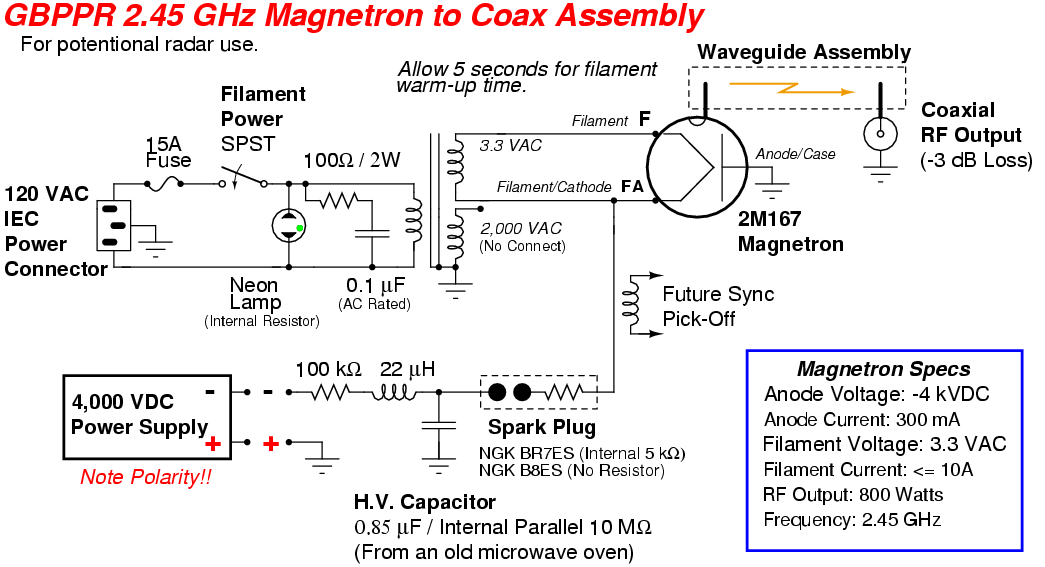
Besides bashing Evil Corley's head in, you've also always wished for an easy way to couple the RF output from a microwave oven's magnetron into standard coaxial cabling. Thanks to the dedicated experimenters working around-the-clock in the GBPPR labs, at least one of your dreams is about to come true!
This project consists of a simple "waveguide-to-coax" transition made from the parts of old microwave ovens. It's probably a good idea to pickup a dozen or so microwave ovens at the thrift store, or from the curbs on garbage night, then rip them all apart for the pieces. Microwave ovens are very robust and the major electrical components almost always still work, even in the "dead" ones. One key component to look out for in your microwave oven quest is one with a long sheet metal waveguide section connecting the output from the magnetron's probe antenna to the cooking chamber. These are fairly easy to find on microwave ovens built during the early 1980s, but as the ovens became physically smaller, this small waveguide section was eventually eliminated. This section of waveguide is crucial, as it already has the proper dimensions for working at 2.45 GHz.
Other components for this project which can be salvaged from old microwave ovens include the high-voltage/filament transformer, the high-voltage capacitor and diode, 15 amp AC fuses or circuit breakers, and miscellaneous bits of high-voltage connecting wires. When salvaging for the high-voltage/filament transformer, try to find one which is physically small, as it only needs to supply the high-current 3.3 VAC filament power to the magnetron. The 4 kV DC power supply will be external. These can be hard to find, so you may end up making your own. Details on a suitable magnetron high-voltage power supply should appear in a future issue of GBPPR 'Zine.
The basis for this particular device is to eventually work it into a personal air surveillance radar system. You know you always wanted one! Well, I think we can pull it off...
It should be possible to monitor your local air space for intruding aircraft, or even incoming rockets. The range and resolution will probably not be very great, and the display still needs alot more work (i.e. somebody write one in software). You should also be able to point it upwards and look for UFOs! Right now, of course, nothing works - so this will be an ongoing project.
As per all our fairly dangerous projects, Digg and Slashdot posters will be immune to the high-voltage and high-energy RF involved while building and operating this device. Seriously. We don't lie.
Sheet metal waveguide section salvaged from an old 1980s microwave oven. For this project, you'll need one at least 8 inches long.
You may also wish to pick up a good pair of Wiss tin snips and other sheet metal working tools. You'll also need a rivot gun and some 1/8 inch diameter stainless steel rivots.
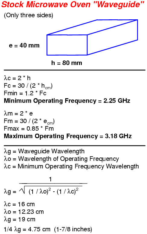
The stock waveguide dimensions are approximately 3.15 inches (80 mm) wide with the sides 1.57 inches (40 mm) high.
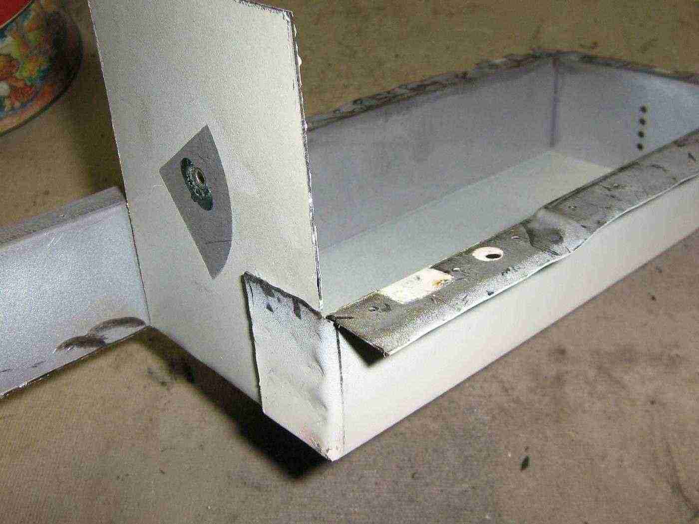
Cut and fold over the open end of the waveguide so it is exactly 7.5 inches (19 cm) long. This is equal to one waveguide wavelength at 2.45 GHz. Try to get ahold of a spot welder to secure the sheet metal flaps. Use rivets or epoxy as a last resort. Harbor Freight Tools has a spot welder (#45689) which works nicely on standard 120 VAC wiring.
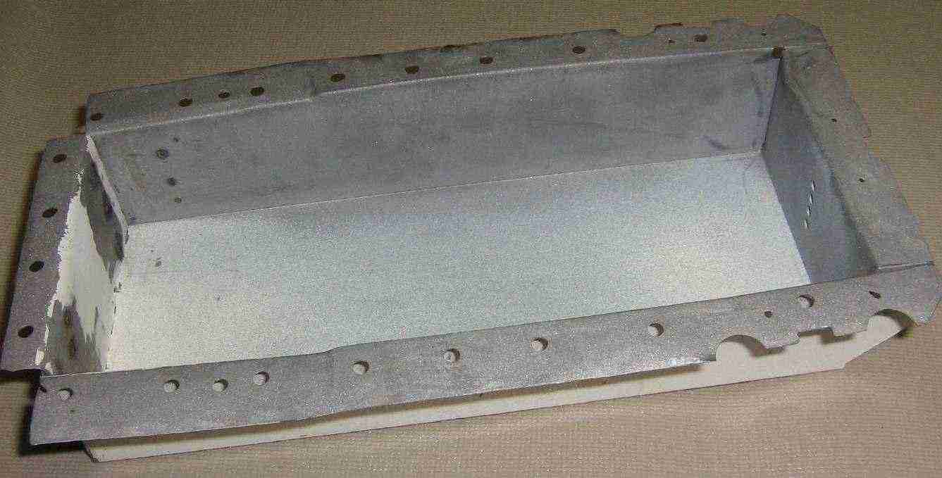
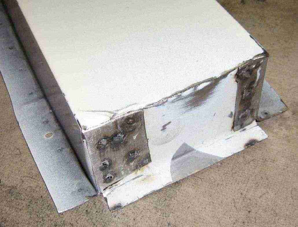
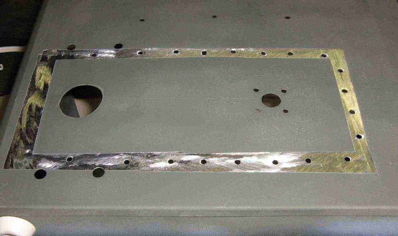
The new waveguide assembly should look something like this. The sealed "new" end is on the left. Drill 1/8 inch diameter holes were the old spot welds on the assembly used to be. These holes will be for rivots to secure the waveguide assembly to the side of an ammo box which the magnetron will be housed in.
Use a Dremel grinding wheel and a small tack hammer to remove any high spots along the waveguide's flange.
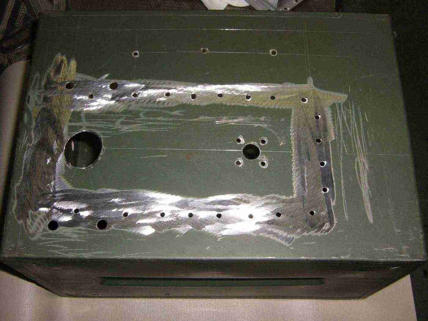
Prepping the ammo box. First layout the waveguide assembly so there is adequate clearance for the magnetron and the N connector pick-off. Mark where the rivot holes should go using the pre-drilled holes as a template. Next, measure 1-7/8 inches (4.75 cm) from the "new" end of the waveguide (opposite of the magnetron). Mark this spot for the center of the N connector. This point is 1/4 waveguide wavelength from the closed end of the waveguide. On the magnetron end, use the holes or notches which should already be in the waveguide as the reference point for centering the magnetron's RF probe. Use this as a reference point when laying out the rest of the holes to drill.
You'll also want to grind away all the paint around where the waveguide will be rivoted against the ammo box. This needs to have a very secure electrical connection for proper RF shielding.
For additional protection from RF leakage, you may wish to add conductive RF fabric to the edge of the waveguide assembly. This will help to seal any dents in the sheet metal which could leak dangerous levels of RF radiation.
Small strips of FerriShield adhesive-backed EMI gaskets are available from Mouser, part number 861-SG060125R-24.
Mask off the section where the ammo box and the waveguide will meet when painting. This will maintain good electrical integrity between the two pieces.
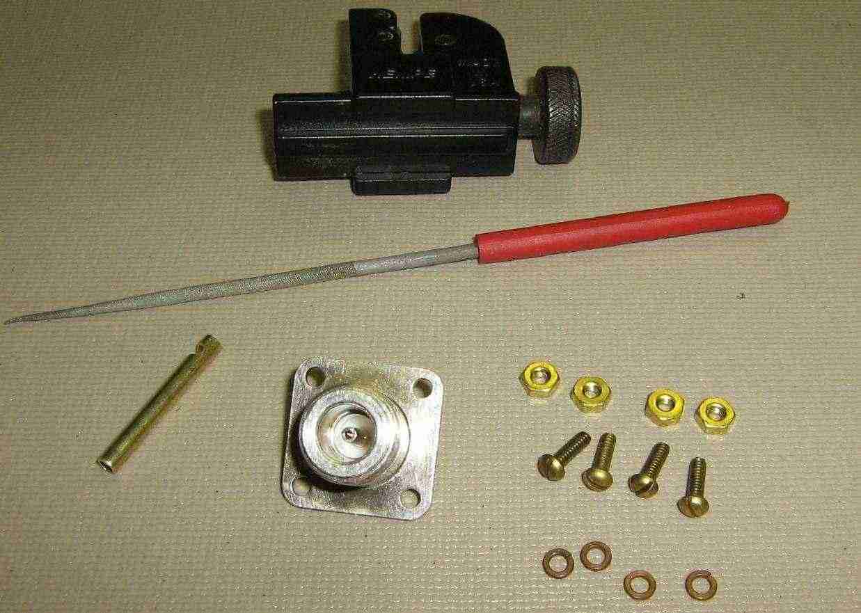
Parts for the N connector RF pick-off. Use a high-quality Teflon dielectric panel-mount N connector and #4 brass mounting hardware. The actual antenna will be a 1-1/4 inch (31 mm) long piece of 1/8 inch inside-diameter brass tubing from the hobby store. File a small notch towards one end of the antenna element to help the solder flow when soldering it to the N connector's center conductor.
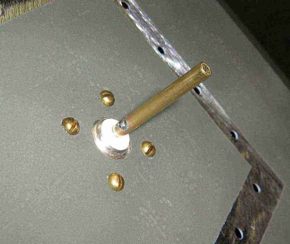
N connector installation.
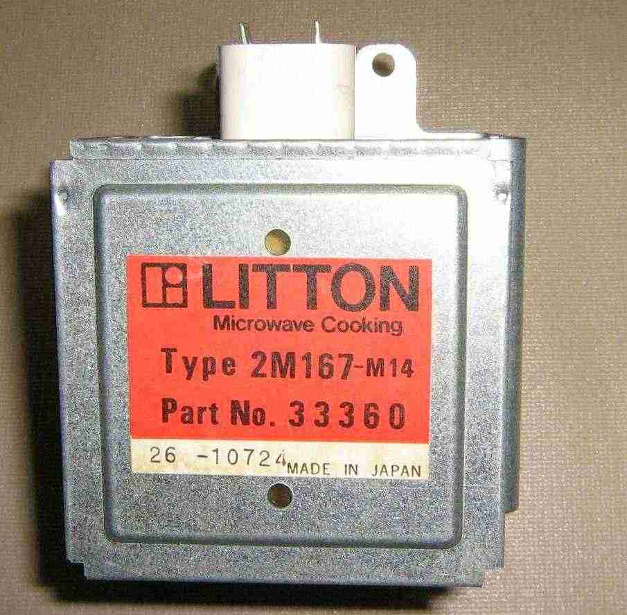
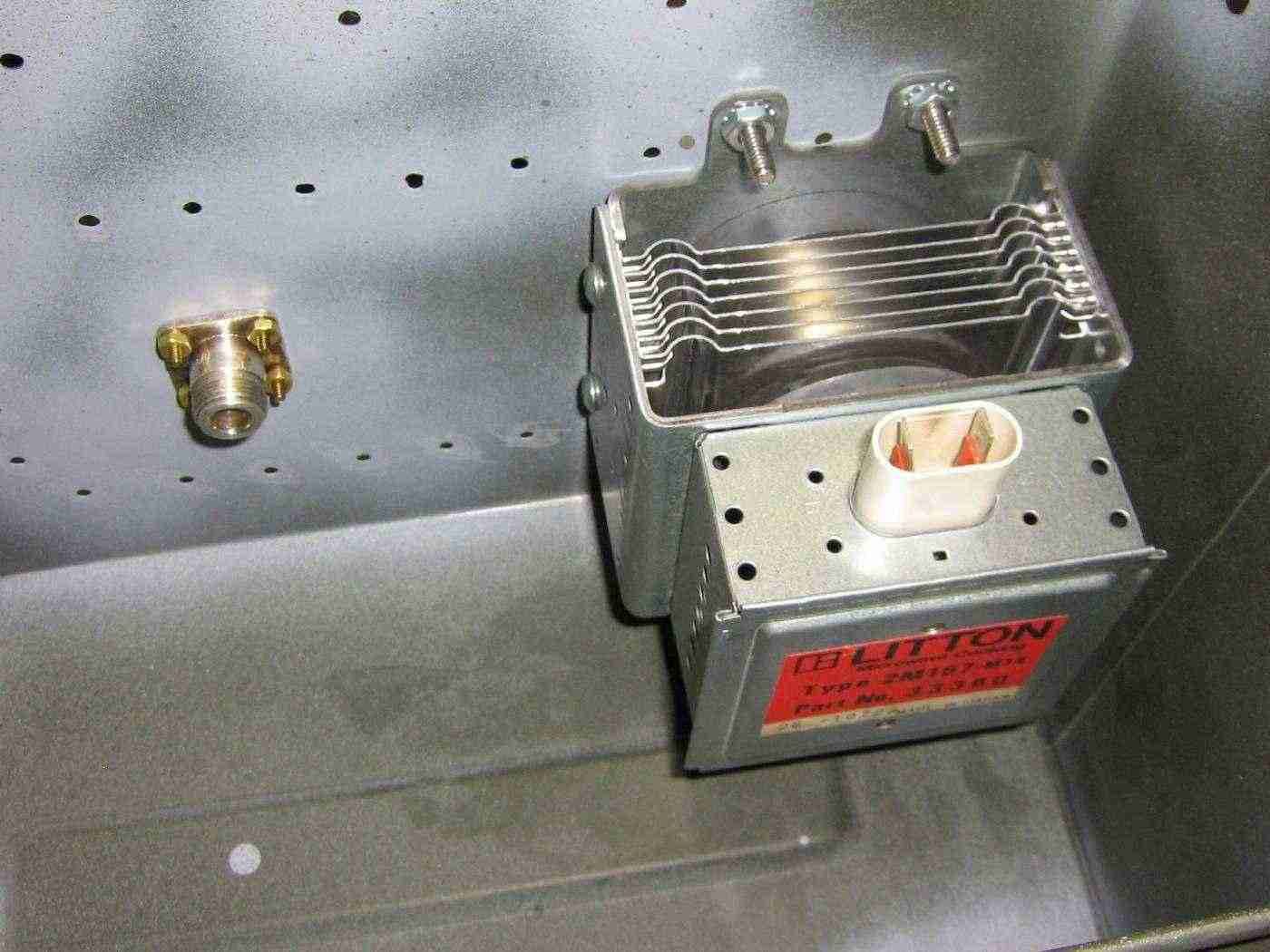
Magnetron used for this project. It's a Litton 2M167-M14. It appears to do around 800 watts CW at 2.45 GHz.
Can you tell I just bought a copy of The Legend of Litton Industries by Jeffery L. Rodengen, ISBN 0-945903-51-0?
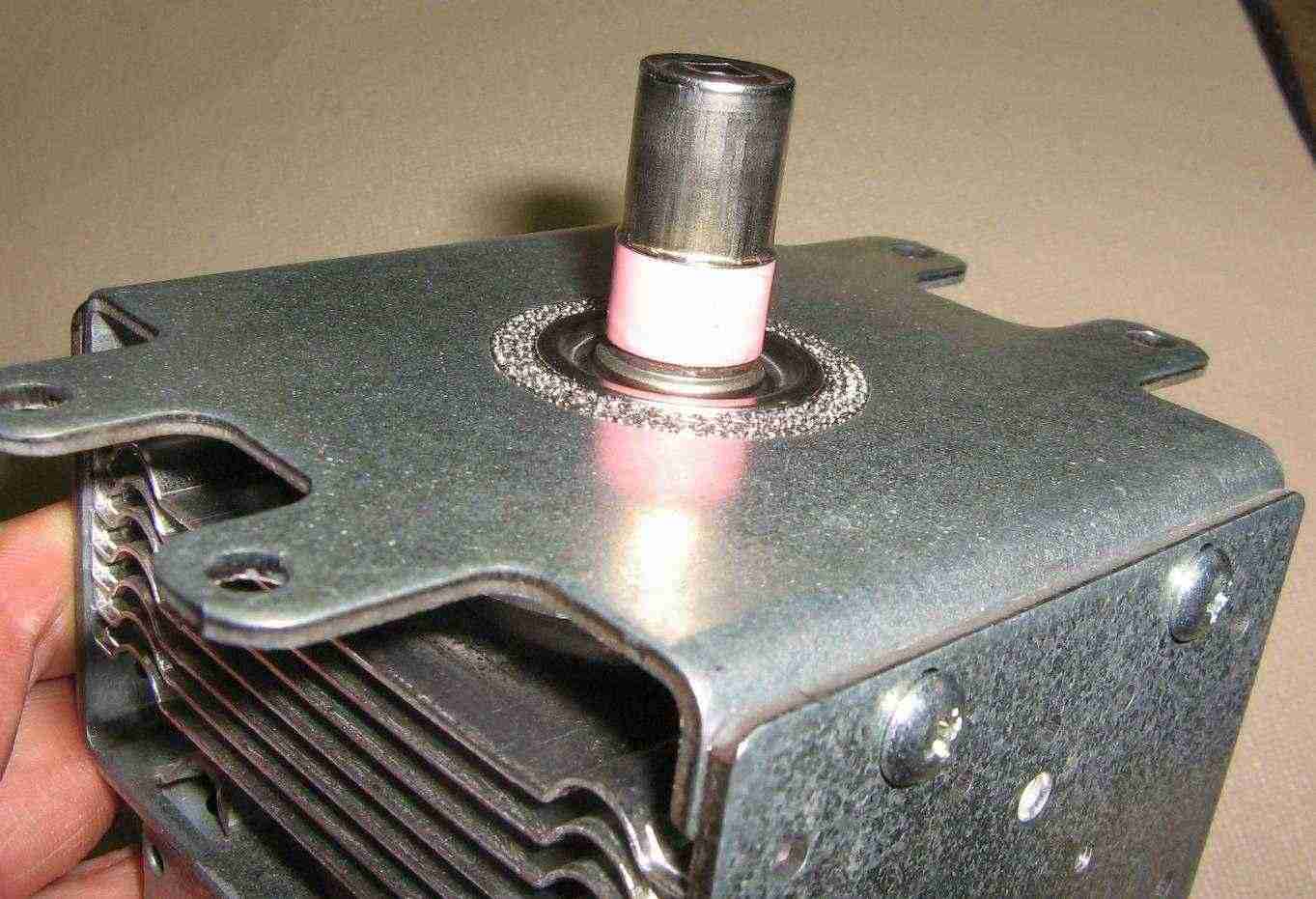
The magnetron's RF output comes from the little ceramic antenna. The metal "cap" acts as a loading capacitor. Note the wire ground mess around the probe.
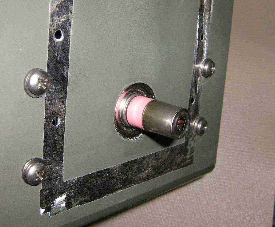
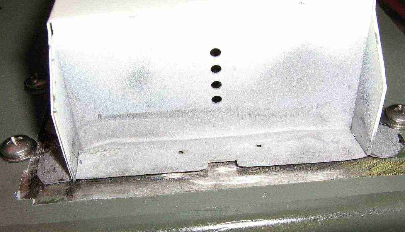
Mount the magnetron as shown. Be sure the grounding mesh around the magnetron's output probe touches an unpainted region inside the mounting hole. This is necessary for proper RF shielding.
Internal view showing the output N connector and the magnetron. There will be around 3 dB of loss with this setup. It can be tweaked for lower loss, but that's alot of unnecessary fussing around. The load mismatch can slighty alter the magnetron's output frequency and also reduce the life of the tube itself.
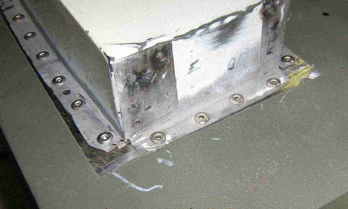
Rivot the waveguide assembly to the outside of the ammo box. Be sure there is a good solid mechanical and electrical seal.
A minor problem securing the waveguide will be around the section where the magnetron is located. It's not possible to use rivots without drilling clearance holes in the magnetron's body. You may wish to use some two-part epoxy putty to secure the sheet metal flaps down.
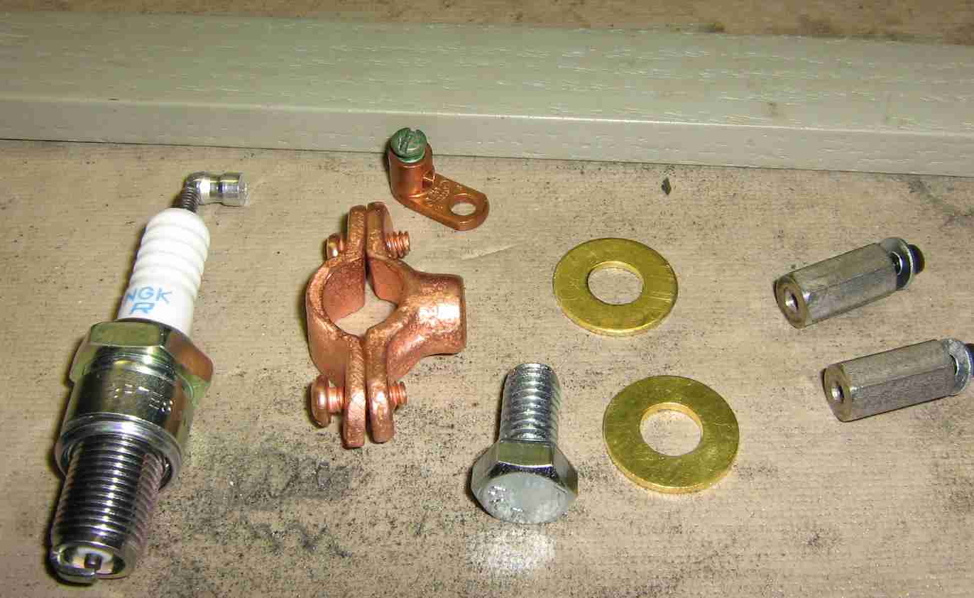
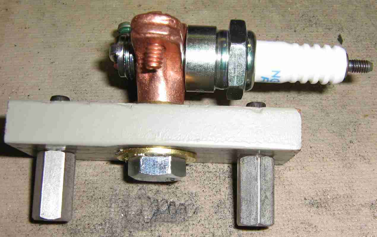
For this project, which is intended to be used as an experimental radar system, we'll be pulsing the magnetron using a spark plug. The spark plug will be secured to a wood insultor using a 1/2 inch copper split-ring hanging clamp. The main thread in the camp is standard 3/8-16. A small ground lug will connect the pulse wiring to the clamp's body.
The spark plug shown here is a NGK BR7ES. The spark plug's internal 5,000 ohm resistor will limit current into the magnetron to prevent damage. Set the spark plug's gap to 0.040 inch (#60 drill bit), or to fire at around 4,000 volts.
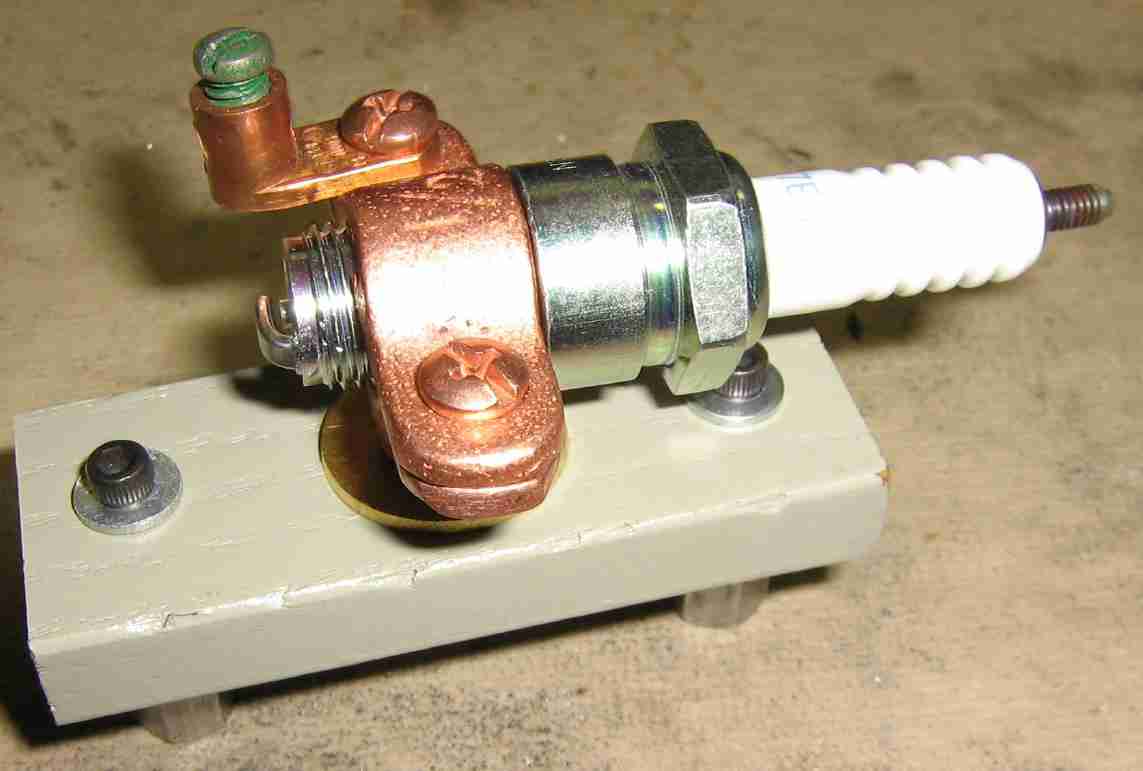
Completed spark plug firing assembly.
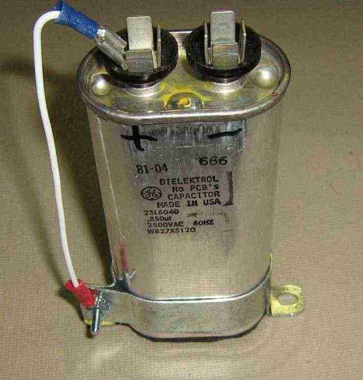
High-voltage capacitor from an old microwave oven. The "positive" side is connected to ground.
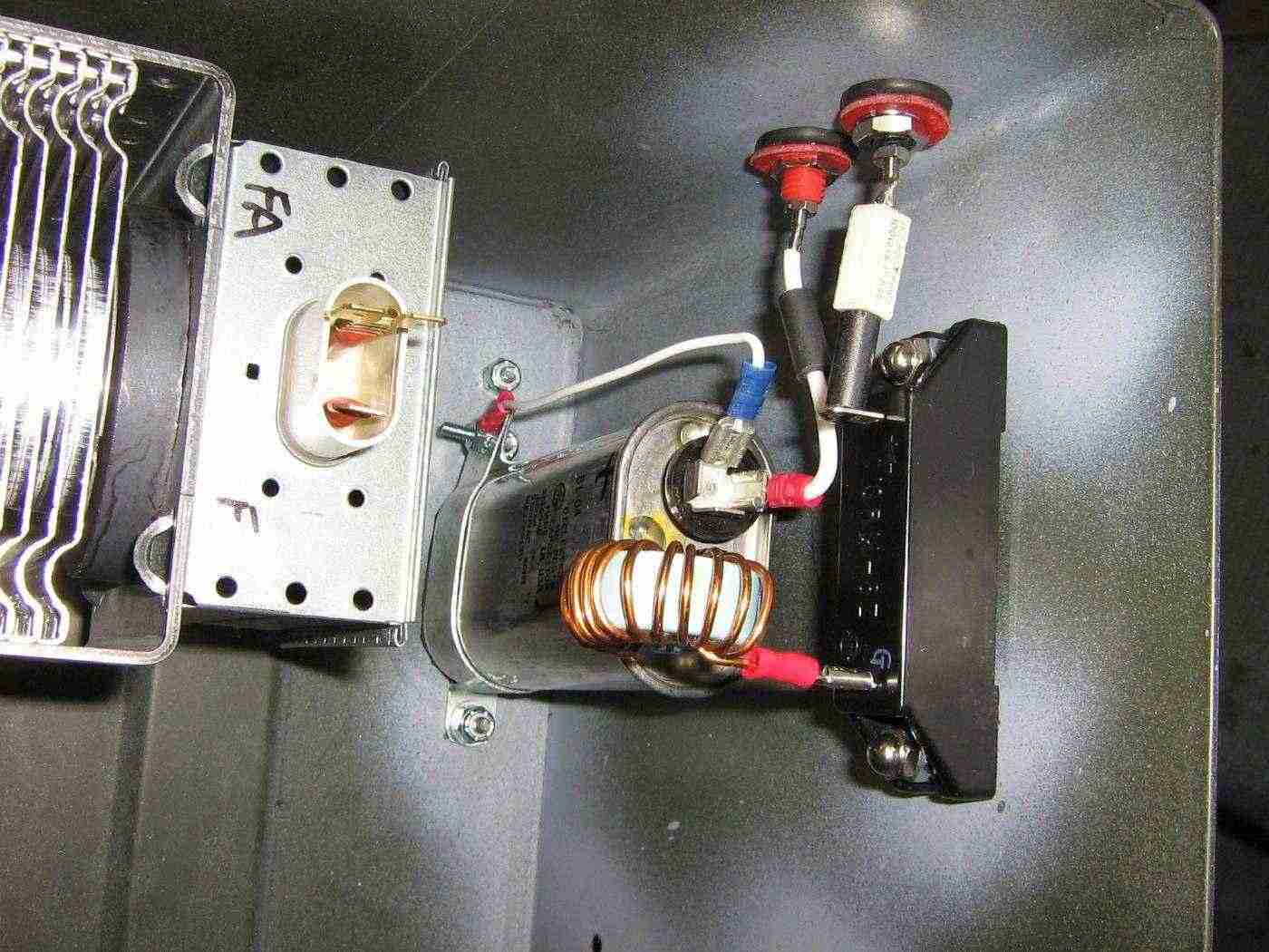
High-voltage input connections. The input banana jack terminals are isolated using rubber grommets. The high-voltage diode is also from an old microwave oven. A 22 µH inductor from an old computer power supply is used as a choke to stop the voltage pulse from effecting the high-voltage power supply. Slip a few ferrite beads over each of the incoming power wires to choke off any voltage spikes.
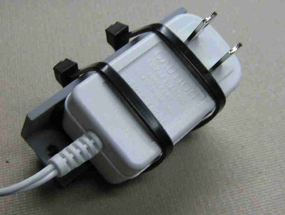
Find an old 12 VDC wall-wart power supply and secure it to a L-bracket. This will be used to power a small fan mounted above the magnetron. Solder the incoming 120 VAC wires directly to the wall-wart's prongs.
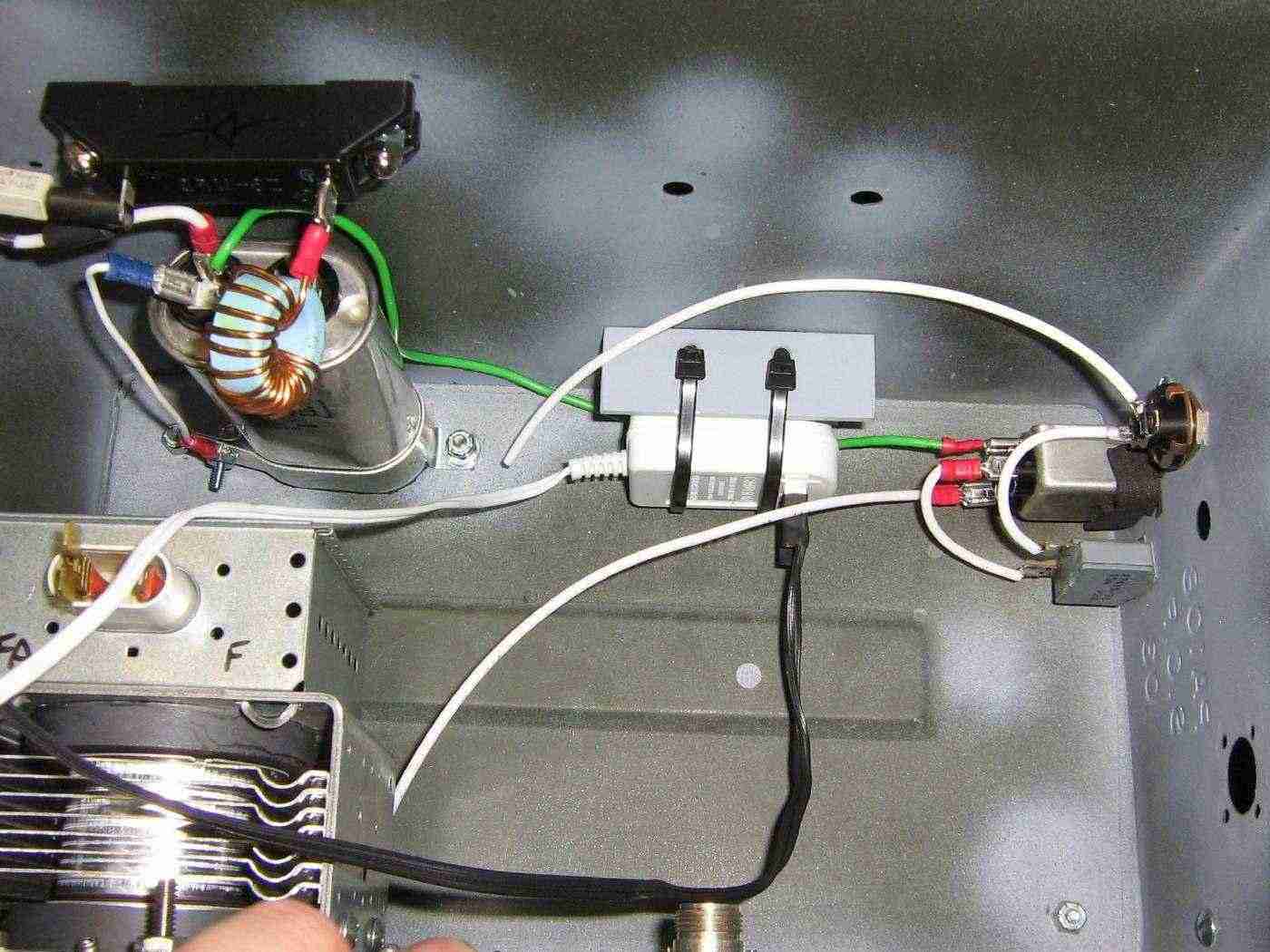
Internal view showing the front panel wiring for the AC input to the filament transformer and also the fan wall-wart power supply mounting.
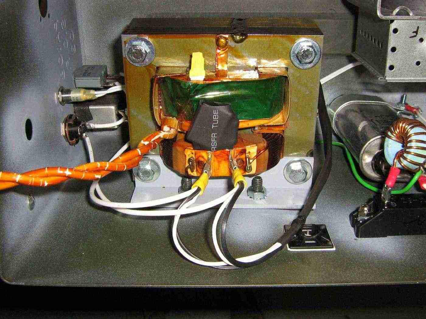
Filament transformer installation. Since only the low-voltage 3.3 VAC filament winding is used, you may remove the high-voltage terminal to prevent accidental shocking. The series 100 ohm resistor and 0.1 µF AC-rated capacitor form a voltage spike "snubber" on the transformer's primary.
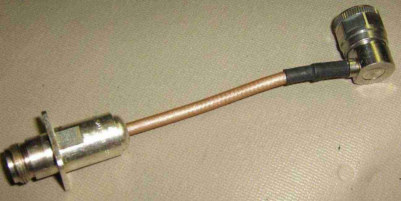
RF output coaxial assembly. Front-panel female N connector connects to a right-angle male N connector with a piece of Teflon dielectric RG-142 coax.
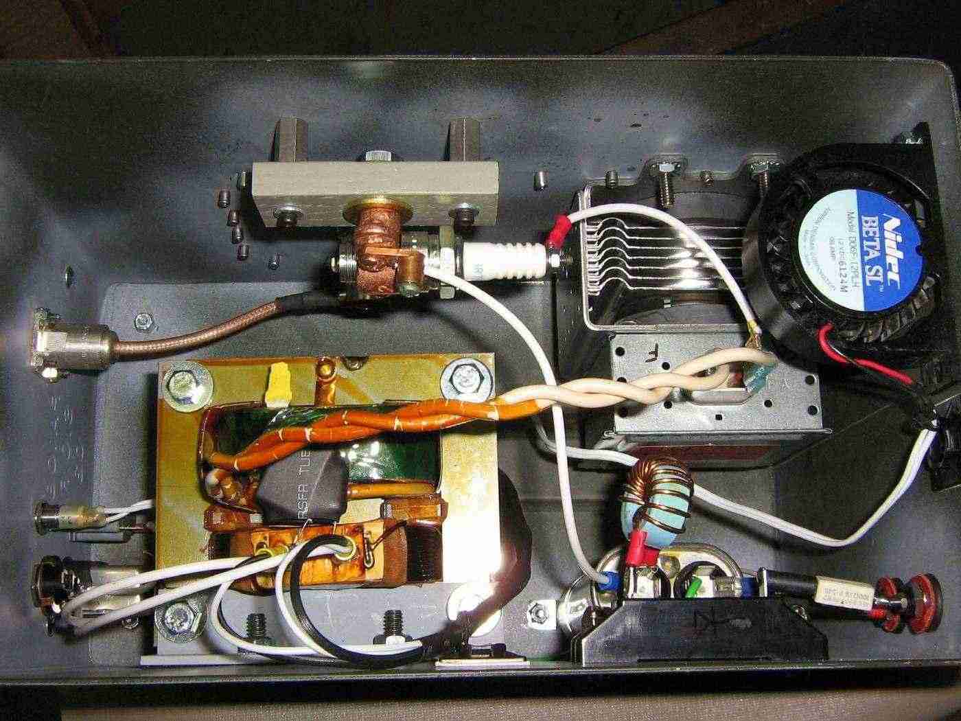
Completed internal view. High-voltage DC power comes in on the lower-right, the AC for the filament transformer on the lower-left. The wire from the screw terminal on the spark plug connects to the cathode terminal on the magnetron. The small fan blows out through a hole in the side of the ammo box.
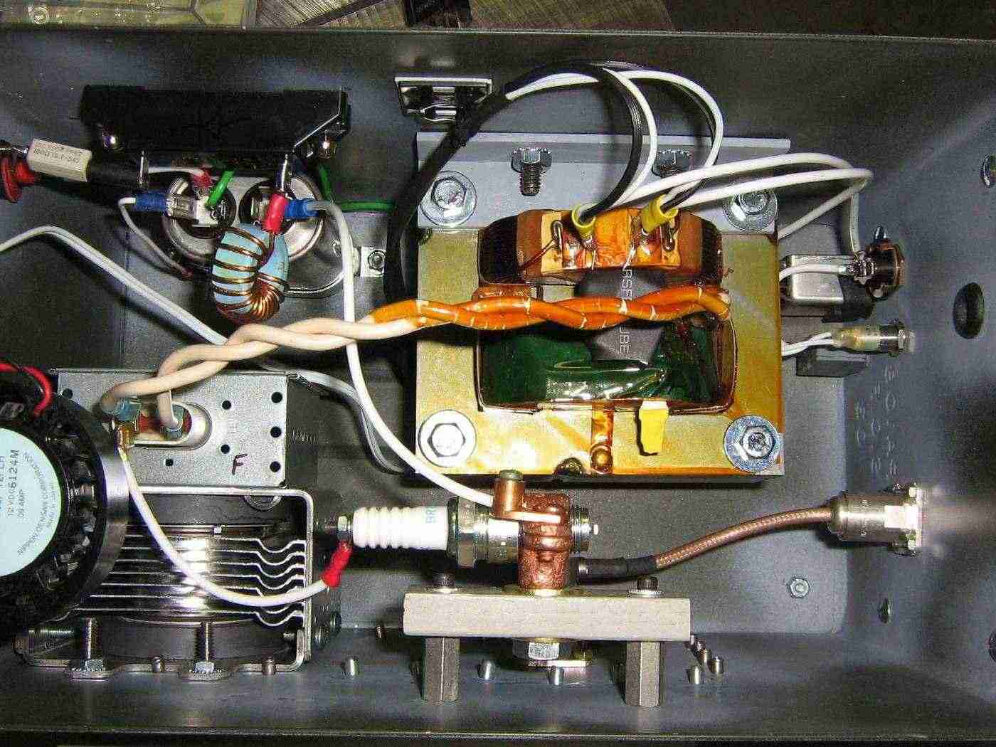
Alternate view. An experimental "sync" circuit will be designed in the future. This should be useful for triggering an oscilloscope for use as a radar display. It will probably consist of a ferrite torroid picking off the magnetron's high-voltage firing pulse.
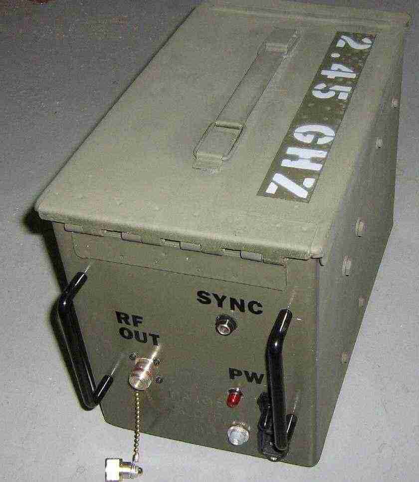
Outside front-panel overview. The SYNC output is a 1/4 inch stereo jack and is isolated from the front-panel using a rubber grommet.
Be sure to only operate the device when the RF output is properly loaded.
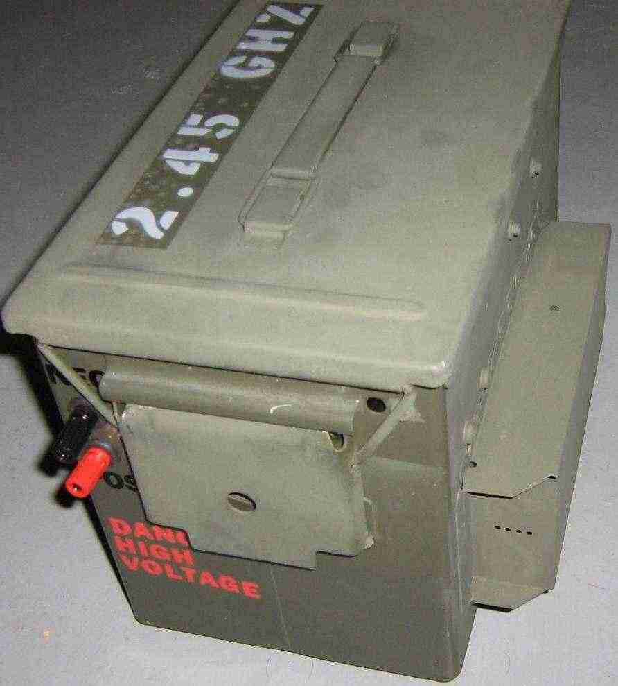
Outside real-panel overview. The small banana jacks were upgraded to larger ones because they started to arc over.
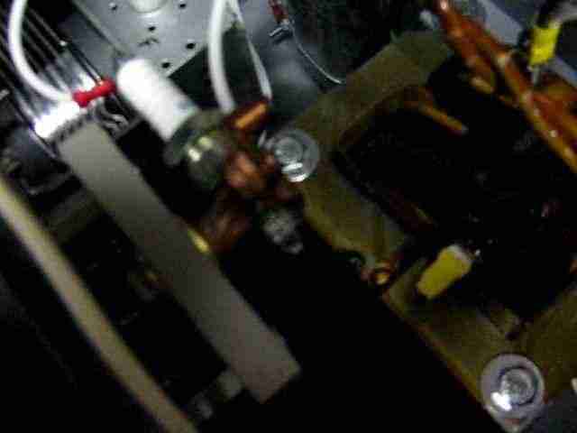
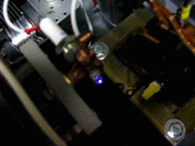
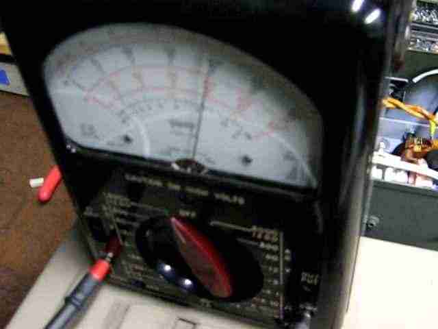
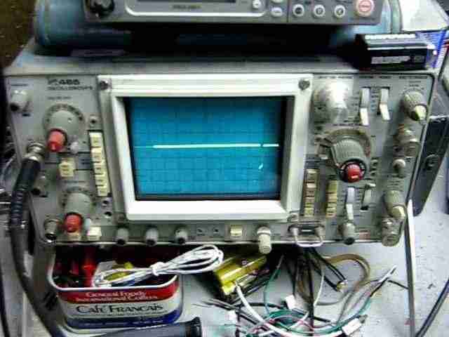
Screen captures from a video of this device in operation. The volt meter is reading around 4,000 volts DC and the oscilloscope is set to 1 volt per division with a time base of 5 milliseconds per division. The coaxial RF output from the magnetron is run into a 20 dB directional coupler terminated with a high-quality 50 ohm load. An additional 20 dB of attenuation is on the forward-coupled output from the directional coupler. This brings the total attenuation to 40 dB.
Be sure to use high-quality RG-8 coax and Teflon dielectric RF connectors when testing and operating this device. This helps to avoid additional RF loss and also contains the fairly high RF operating voltage.
Every time the high-voltage capacitor charges, the spark plug "fires" and the magnetron emits a RF pulse. Be sure to let the filament warm up for a few seconds before applying the high-voltage to the magnetron.
The oscilloscope measures a negative downward spike of about 2 volts during each RF pulse. When factoring all the attenuation, this corresponds to a RF output of approximately 400 watts. The pulse widths are actually quite longer than you'd like, measuring in the hundreds of microseconds or even milliseconds in some cases. The pulse repetition is also quite spotty. We'll just call this an electronic countermeasures countermeasure for the time being.
This video is available here: Magnetron-to-Coax.wmv (966k WMV)