Outside overview. It is built into the case of an old GRA-39 radio control set. The two push-terminals on the left are for the +12 VDC power supply, the RF output (antenna) is a N connector, with a dust cap. The two toggle switches control the system's power and the hopping speed. The gray things are dust boots. The red LED is a power indicator and the green LED lights everytime the system transmits. The big, black light is not used.
The case is painted camel-humper beige. The black sticker lettering is protected with clear finger nail protector, really.
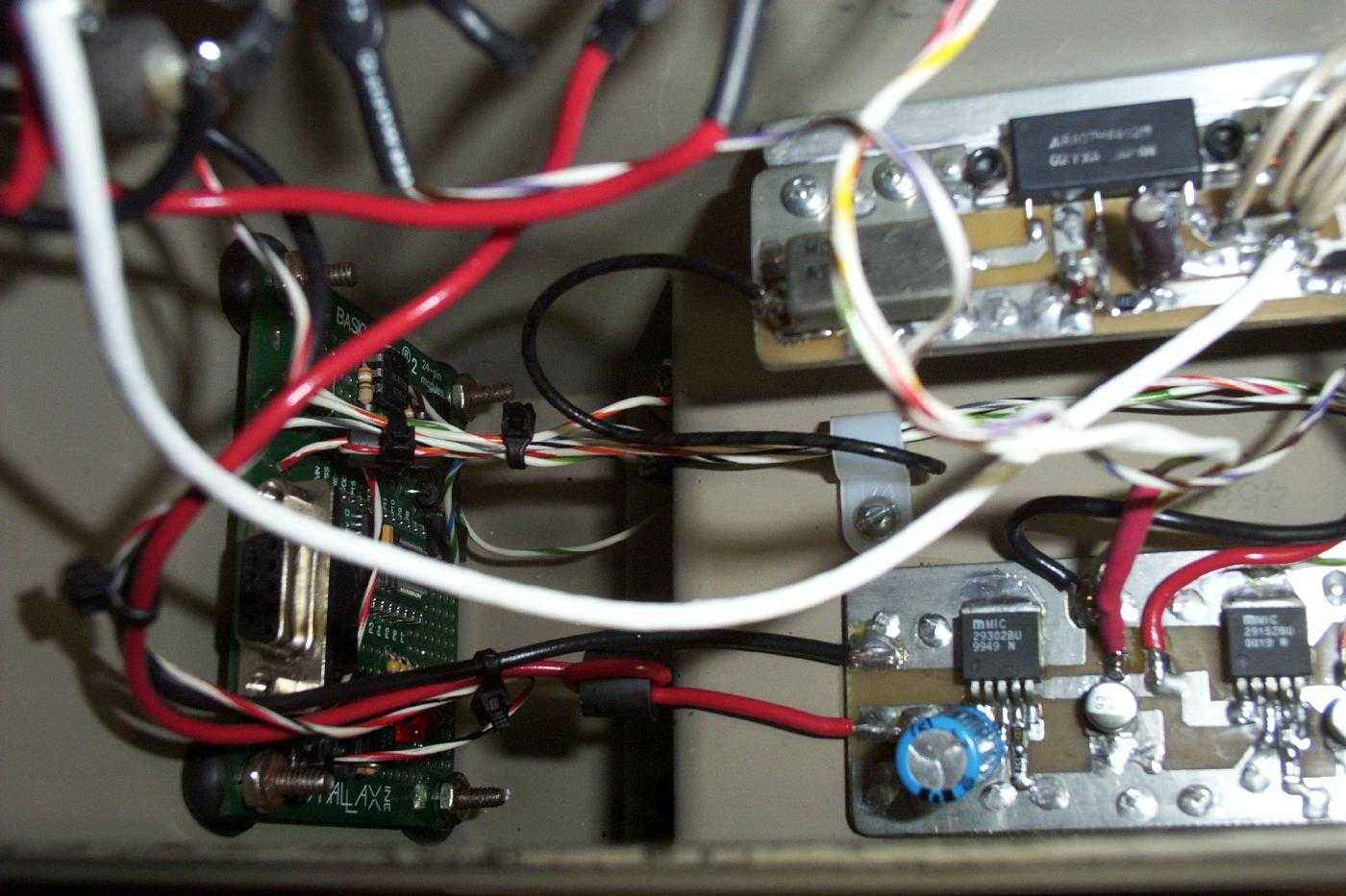
Internal overview. The BASIC Stamp 2 microcontroller on mounted on the left using little rubber washers and stainless steel hardware. The RF power amplifier is mounted in the middle on a block of aluminium, to act as a heatsink. The wires and coax cables are secured with zip-ties and plastic holders.
Behind the panel overview. All the wire connections are sealed with heatshrink and all the stainless steel mounting hardware is sealed with Loctite. Silicon sealant is also used around the N connector, fuse, LEDs, and the switches to help seal them against dust/moisture.
Close up picture of the low-dropout voltage regulator board. This takes the incoming DC voltage and regulates and filters it to clean +12 VDC and +6 VDC for powering the RF power amplifier and the controller/FRS radio, respectively. The Micrel MIC29302BU is configured for +12 VDC and the MIC29152BU is configured for +6 VDC. See their data sheets for more info on them.
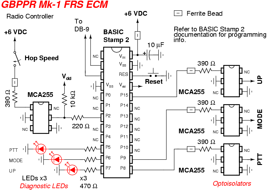
Another internal close up picture showing the BASIC Stamp II microcontroller and it's PC board.
Note the rubber washers and the secured wires.
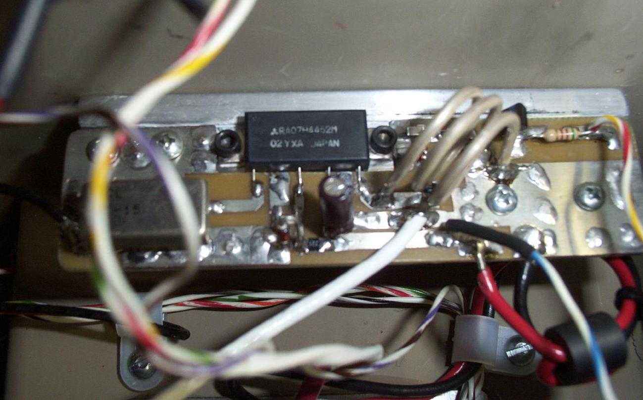
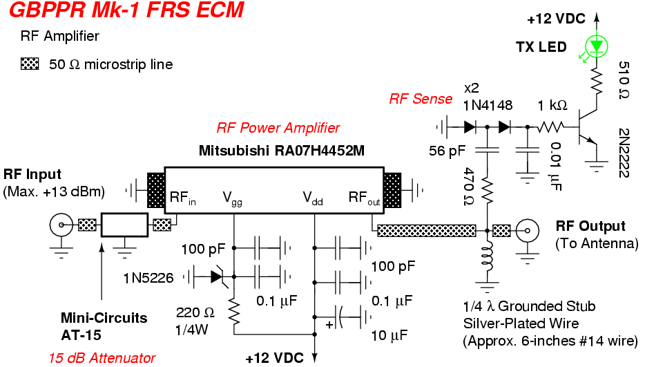
Close up picture of the RF power amplifier. It is based around the Mitsubishi RA07H4452M 7 Watt, MOSFET RF module. The RF input is from the FRS radio - through a 15 dB attenuator. The RF power control line (Vgg) is always set to around 3 volts via a Zener diode. The big silver-plated copper wire loop on the RF output is a grounded 1/4-wave stub. This helps to prevent any static electricity on the antenna from damaging the RF amplifier module. A simple diode/transistor/LED is used as a RF sense for a "transmit" indictor light.
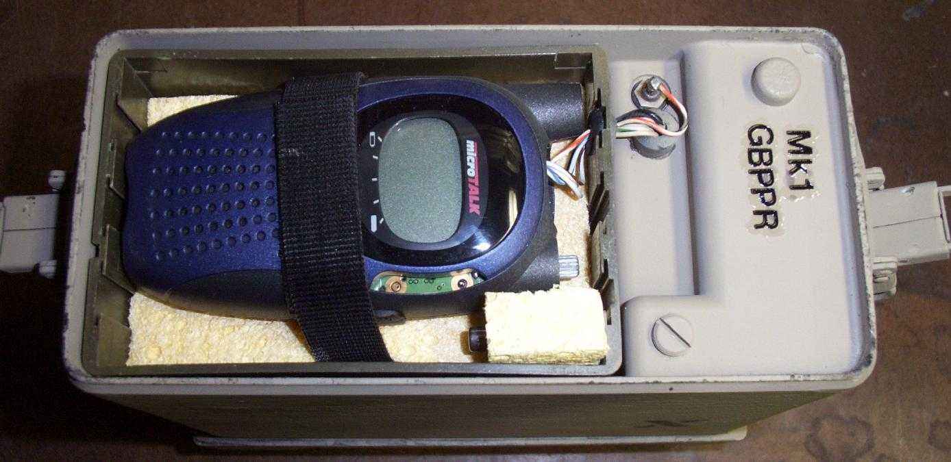
A Cobra PR950DX FRS radio is used as the exciter. The "PTT", "MODE", and "UP" buttons are controlled via the BASIC Stamp. The FRS radio is mounted in the bottom compartment of the GRA-39 case and is resting on some sponges. A second little sponge holds a spare fuse.