This is a highly experimental device which should be useful for Explosive Ordnance Disposal (EOD) technicians to help locate an Improvised Explosive Device (IED) via the electromagnetic radiation given off by any timing clock signals in the detonator.
Most consumer digital watches (or timers) use a 32.768 kHz crystal for the timebase. This project consists of a tuned ferrite loop antenna and a direct conversion receiver with a local oscillator frequency of 38 kHz. This mixes with the incoming 32.767 kHz signal to produce a "beat tone" of 5,232 Hz. The presence of this tone when sweeping a suspicious package is a good indication that a digital watch or timer is nearby. Since the final "signal processing" is done in the operator's head, the signal detection potential is very high.
There is just one big problem with this particular design. It doesn't work too well. The initial testing was done using a signal generator under "lab" conditions. It all seemed to work perfectly... But, in real-world testing, there was so much background noise that deciphering the converted audio tones was very difficult.
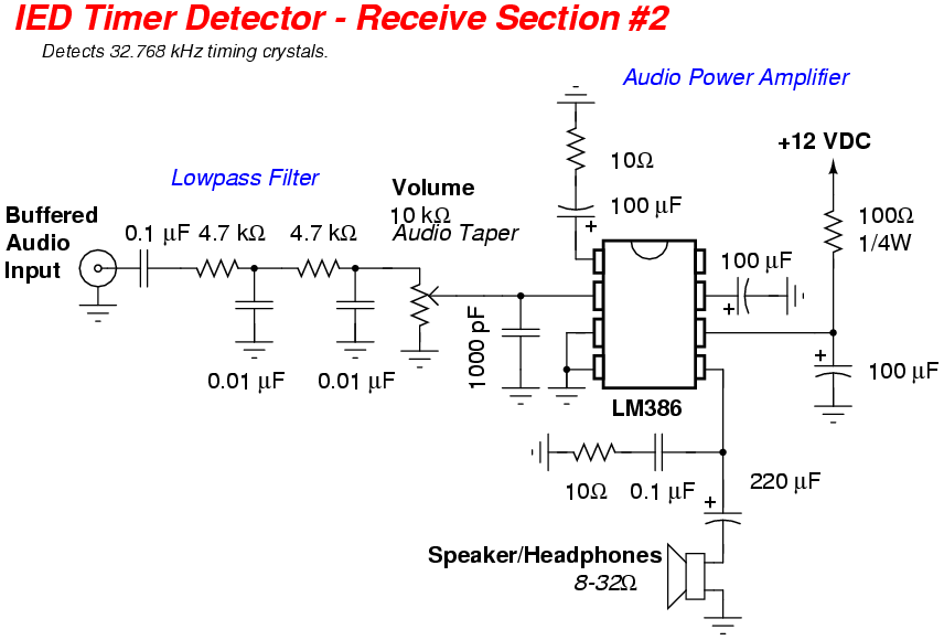
That said, this device can be a useful starting point. Most likely, the remote head circuit will need to be redesigned to include a bandpass crystal filter, and the receiver's post-mixer amplifier and filter section should be tweaked to use something other than a passive resistor/capacitor network and a LM386. The LM386 can burst into oscillation in this particular application if the volume is too high.
This project will revolve around a C-MAX CMA-60-100 ferrite rod antenna from Digi-Key, part number 561-1001-ND. A 0.01 µF and 3900 pF capacitor will be placed in parallel across the ferrite antenna's winding to make it resonate at around 33 kHz. The ferrite antenna will then be placed inside a piece of copper pipe to act as an electrostatic shield. This forces the entire ferrite antenna to always be at the same "ground" potential. A slit will need to be cut lengthwise along the copper pipe. The ferrite antenna feeds a Maxim MAX437 op-amp which has its gain fixed at around 60 dB. The MAX437 has very good ultrasonic capabilities, and is ideal for this application. The MAX437 and buffer circuit will be housed in a small piece of galvanized water pipe to act as both a handle and EMI shield. This entire unit will be referred to as the "remote head."
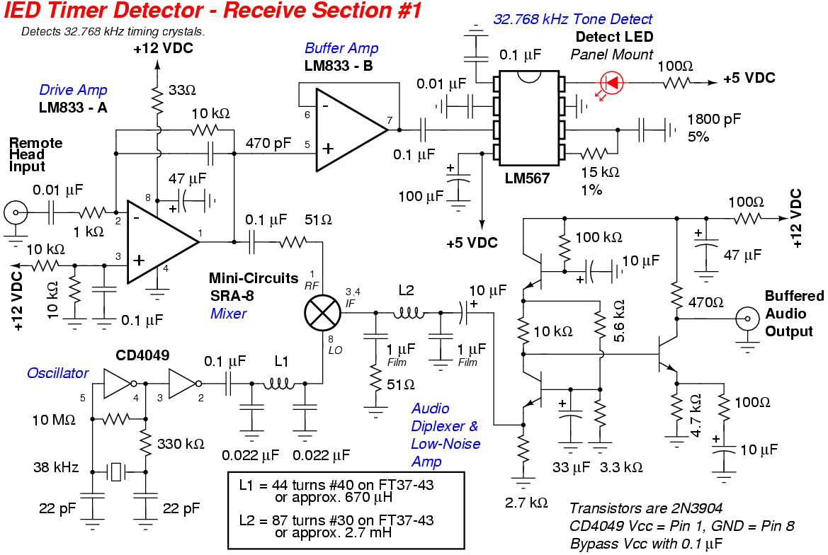
The remote head is then connected to the receiver section. The receiver consists of a standard direct conversion design which is described in more detail in the book Experimental Method in RF Design. This particular receiver uses a local oscillator based around a 38 kHz crystal salvaged from one of those CD-to-FM radio converters. You may have to look around a little for an older model which uses the infamous Rohm BA1404 FM stereo transmitter IC. The 38 kHz crystal will be the little silver cylinder between pins 5 & 6. The CD4049-based 38 kHz oscillator will then feed the local oscillator port on a Mini-Circuits SRA-8 mixer via a lowpass filter / impedance matching network. The SRA-8 was chosen because it has very good low frequency response. This is a requirement for this project to work correctly. The IF audio diplexer and post-mixer designs are straight from Experimental Method in RF Design. The final audio amplifier is a LM386 tweaked to give about 70 dB of additional gain. This is a total hack, as this entire circuit is still somewhat experimental. Ideally, after the post-mixer amplifier, a good audio bandpass filter and stable, low-noise audio amplifier should be used.
The final output audio signal is sent to a pair of low-impedance headphones wired for mono. Any additional signal processing will be done by the user, or even a computer. Using a computer to analyze the received tones is probably the best method. A 8 ohm to 1,000 ohm matching / isolation transformer should be used to feed the computer's soundcard, and to avoid any interference from ground loops.
Remote head construction. You'll need a five inch piece of 1-inch diameter galvanized pipe, a 1-inch to 1/2-inch reducing coupler, and a 1-inch end cap. You'll also need a six inch piece of 1/2-inch diameter copper pipe, a 1/2-inch CPVC end cap, and a 1/2-inch CPVC MIP adapter screw-in thingy.
Using a Dremel tool, cut a 1/4-inch wide slot along the entire length of the copper pipe. Debur the sharp edges with a wire wheel attachment.
Next, is modifying the C-MAX CMA-60-100 ferrite antenna. Unsolder the stock 4700 pF capacitor and solder in place a parallel 0.01 µF and 3900 pF capacitor. Slide some rubber washers on for additional protection. Be sure there is enough slack in the antenna's wires so it can screw onto the reducing coupler.
Cover the ferrite antenna assembly with some heat shrink tubing.
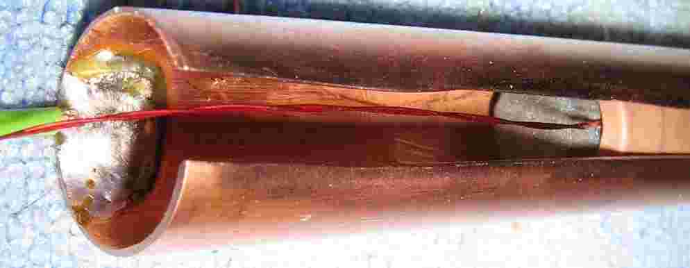
Slide the antenna assembly into the copper pipe, leaving about one inch from the end. Apply some Gorilla Glue to hold it all in place. Also, now is the time to solder a ground wire to the copper electrostatic shield.
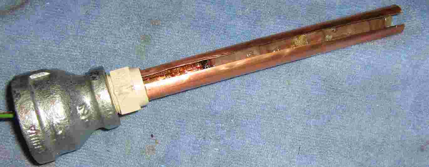
Assemble the parts as shown. A piece of heat shrink tubing should be placed over the copper pipe to help seal and protect everything.
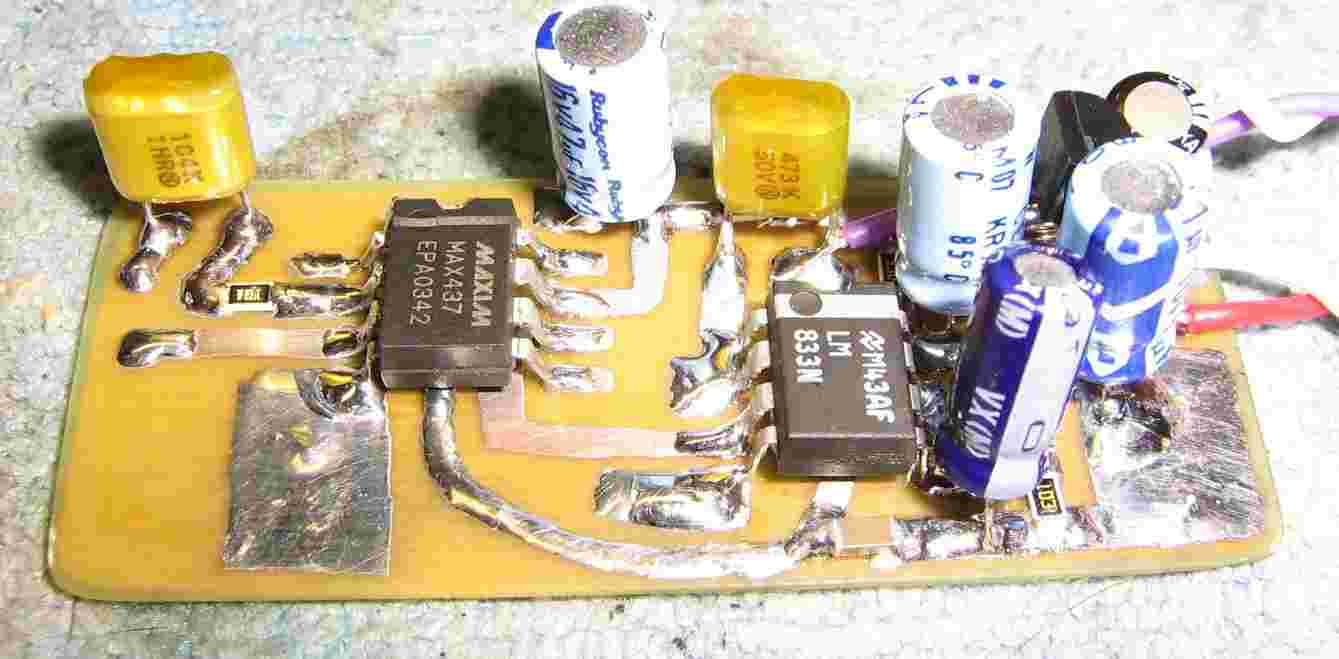
Remote head circuit board. The ferrite antenna connections are on the left. The main pre-amplifier is a Maxim MAX437, which feeds a LM833 buffer op-amp. The second LM833 op-amp is used as an active bias for the MAX437. The remote head's output signal and DC power come via a 2-wire shielded microphone cable and a standard stereo 1/4-inch jack.
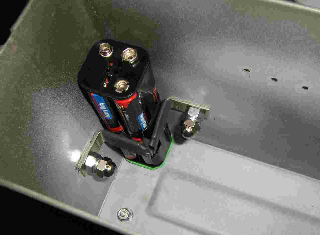
Receiver power supply. Eight "AA" batteries in a plastic holder from Radio Shack. Mount it to a corner in an ammo box using two L-brackets and some art foam for protection.
Reciever circuit. Input is from the top left, into another LM833 buffer op-amp. This feeds both a LM567 tone decoder and the RF port on the Mini-Circuits SRA-8 mixer. The 38 kHz local oscillator signal is generated by a CD4049 hex inverter and is lowpass filtered and impedance matched to the LO port on the SRA-8. The IF output on the SRA-8 is sent to an audio diplexer and post-mixer amplifier, before going to a passive RC lowpass filter, and then on to the final LM386 audio amplifier. Solid circuit construction practices are needed for correct operation of direct conversion receivers. Be sure that the entire receiver circuit is well shielded. An old MMDS downconverter case was used for this project.
Overall receiver internal view. Main front panel controls are on the left. The 10 kohm volume potentiometer also serves as the power switch. There is also a green power LED.
Overall view. The remote head connects to the receiver section with a short piece of shieled microphone cable with 1/4-inch stereo jacks.
The "tip" carries the received 32.768 kHz signal and the "ring" carries the +12 VDC remote head power.