An ultrasonic technical surveillance device is a device for the covert interception of audio which is transmitted, via an inaudible 40 kHz carrier frequency, to a remote listening post. The use of ultrasonic frequencies is a very effective way to prevent any detection of your surveillance bug.
The ideal use for ultrasonic technical surveillance devices is during outdoor or large indoor operations. Ultrasonic waves are fairly directional (about 15° beamwidth), but are easily attenuated. Doors, glass, Plexiglass, etc. will block ultrasonics (to varying degrees) but they can seep through any cracks around windows or under doors. For more information on using ultrasonic surveillance devices, purchase the book The Basement Bugger's Bible by Shifty Bugman.
Ultrasonic tranducers operating at 40 kHz are now quite easily found. A "clean" source of these transducers is from old motion detectors or security alarms. Some of which where carried by Radio Shack (Part # 49-303A) back around 10-20 years ago. New Kobitone 40 kHz ultrasonic tranducers are available from Mouser Electronics, part numbers 255-400ER18 (receive) and 255-400ET18 (transmit). There is actually no difference between the transmit and receive transducers. Most consumer 40 kHz transducers operate at a maximum peak-to-peak voltage of 20 volts, but some can operate at up to 100 volts. The higher the applied voltage, the higher the output sound pressure, and the farther the transducer will transmit. Also, their frequency deviation is limited, so don't expect "HiFi" audio quality. Maximum deviation is only around 1.5 to 2 kHz. The received audio quality sounds much like cheap FRS radios. Any bass frequencies will also need to be heavily attenuated.
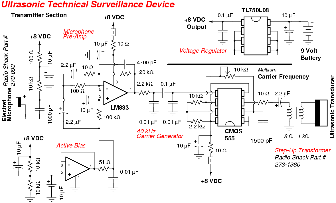
Referring to the transmitter schematic... Be sure during operation that the microphone's little air hole is not obstructed. Experiment with the electret mic's bias resistor (10 kohm) to improve the signal-to-noise ratio. The mic's audio is fed into one-half of a LM833 op-amp. This op-amp is configured to have about 40 dB of gain in the "audio band" of frequencies. The 3 dB frequency roll-off is around 1.7 kHz. The other half of the LM833 acts as a split-rail active bias for the first op-amp. The output of the LM833 is then passed through a RC low-pass filter to remove any remaining ultrasonic frequencies. This processed audio signal is finally fed to pin 5 of a CMOS 555 timer operating near 40 kHz. Adjusting this center frequency is the most critical aspect of this device. The 555 timer's center carrier frequency is "tweaked" via a multiturn 10 kohm potentiometer. Try to use a multimeter which has a frequency counter to help in any adjustments. The use of a CMOS 555 timer is recommended to avoid generating any power supply "spikes" which can interfere with the transmitted audio quality. The output of the 555 timer is a series of square waves centered near the 40 kHz resonant frequency of the transducer. You'll want to then lower the 555 timer's frequency slightly to allow the receiver transducer to recover the audio via "slope detection." If you don't know what that means, just adjust the 10 kohm pot until the audio quality is the best. This new output signal (pin 3) is pulse-width modulated by the input audio signal. It is then isolated and fed into a 8 ohm to 1,000 ohm impedance matching transformer (Radio Shack Part # 273-1380). This is a quick way to increase the voltage applied to the transducer without resorting to using any current-hog active components. The transformer's output is then applied to the ultrasonic transducer. Be sure to isolate the transducer's ground tab (and body) from the rest of the circuit if you use the step-up transformer. For "limited space" covert applications, the 555 timer's output can be run directly into the ultrasonic transducer.
A Texas Instruments TL750L08CD low-dropout voltage regulator (Digi-Key Part # 296-8004-5-ND) provides a stable +8 VDC for the entire circuit when powered from a standard alkaline 9 volt battery. Current draw for the entire ultrasonic transmitter is around 13 mA.
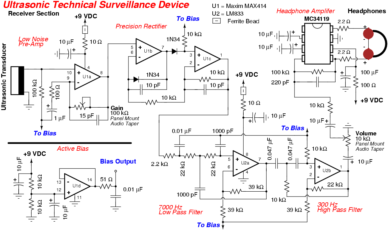
Referring to the receiver schematic... The receive ultrasonic transducer is DC coupled directing into one of the four op-amps on the Maxim MAX414 (Digi-Key Part # MAX414CPD-ND). The MAX414 was chosen because it can easily handle about 60 dB of gain at 40 kHz. A common TL074 quad op-amp will also work, but the gain will only be around 40 dB. The output of that op-amp is then sent to a precision full-wave rectifier circuit using two op-amps and two 1N34 diodes. This converts the modulated 40 kHz signal directly into a varying DC voltage via a method called slope detection. As the transmitter's transducer is modulated on-and-off its resonance peak, the receiver's transducer also outputs more or less voltage. This varying DC voltage is the recovered audio from the microphone. This recovered audio signal is then low-pass filtered using one-half of a LM833 and the other half as a high-pass filter. This removes any remaining low-frequency rumbles and high-frequency hiss. Finally, the audio signal is applied to a low-noise MC34119 headphone amplifier. The receiver runs off a standard alkaline 9 volt battery and the current draw is around 63 mA.
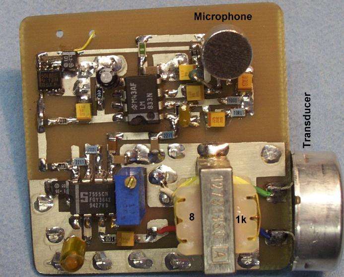
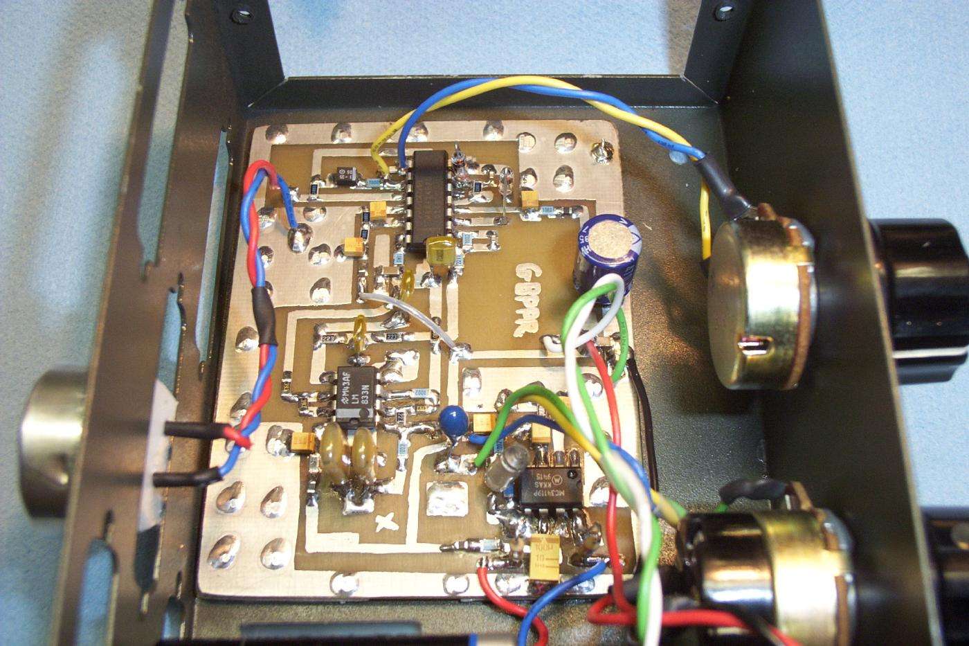
Ultrasonic transmitter overview. Clockwise from the upper-left... TL750L08CD voltage regulator (surface mount), LM833 and supporting passive components, the electret microphone, the 40 kHz ultrasonic transducer (note isolation), the 8 ohm to 1,000 ohm impedance matching transformer, and finally the CMOS 555 timer and its 10 kohm trim pot. A 9 volt battery clip is under the PC board and is not shown.
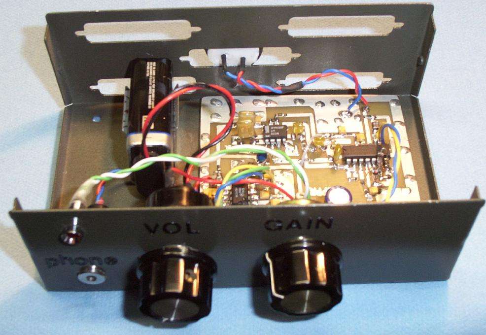
Ultrasonic receiver overview. Case is an old printer switch. Front panel contains a headphone jack (PHONE), volume control (VOL), and receiver gain control (GAIN). The receive transducer and PC board are held down using double-sided foam tape. This helps reduce any noise caused by vibrations.
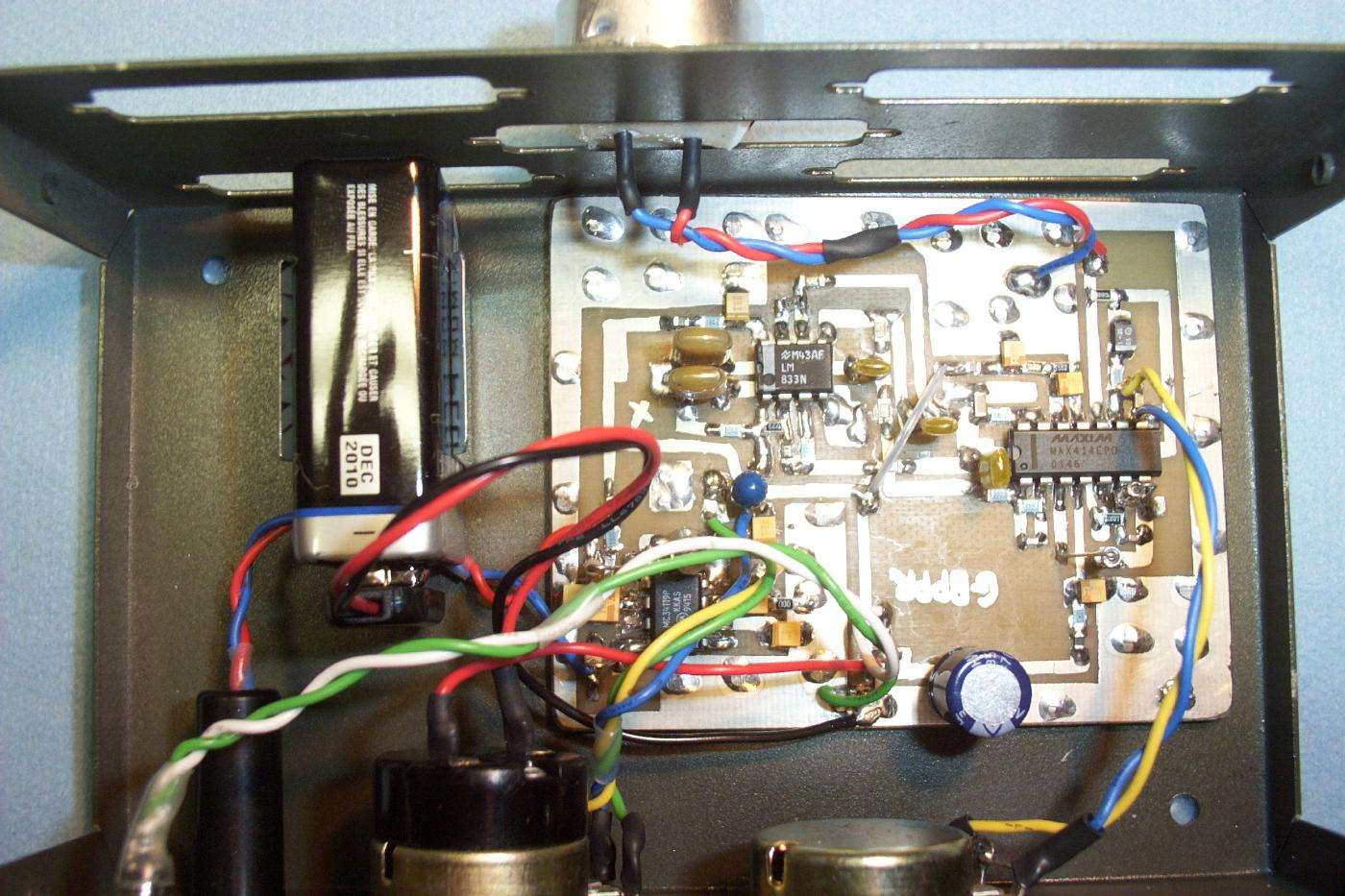
Another overview. Clockwise from the upper-left... LM833 that forms the high-pass/low-pass audio filter, the receive transducer is above that, the Maxim MAX414 quad op-amp, +9 VDC input, and the MC34119 headphone amplifier. Be sure to twist the wires leading to the control pots, the transducer, and the headphone jack. The 10 kohm VOLUME pot has an integrated SPST on/off switch.
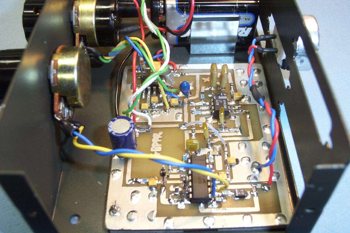
Side view. One bug on this particular unit is that the MAX414 breaks into oscillation when the GAIN control pot is at maximum. It does this even with twisted control wires and a good circuit ground plane, so be careful.
Also be sure to use germanium 1N34 or 1N60 diodes in the full-wave rectifier portion of the ultrasonic receiver. These have a lower voltage drop (~200 mV) than the common silicon 1N4148, 1N914, or 1N4001 diodes (~700 mV). Matching the diode's forward voltage drop is not necessary, but useful for those "precision" applications.
Alternate view. A Motorola MC34119 headphone amplifier (lower right) is used instead of a normal LM386 because of its lower noise figure. An easy-to-find equivalent for the MC34119 is a NJR NJM2113 (Mouser Part # 513-NJM2113D). The output of the MC34119 is a balanced signal. Connect one side to the tip on a stereo headphone jack and one side to the ring. Do not connect the headphone shield (sleeve) to circuit ground! Leave the ground pin on the stereo headphone jack open and be sure the jack is plastic or isolated from the metal case. The series 2.2 ohm resistors pad the output impedance of the MC34119 when driving low-impedance headphones.