Overview of the "X10 Model No. VR36A 2.4 GHz Wireless Video Receiver" for use with X10's wireless camera systems operating in the unlicensed 2.4 GHz band.
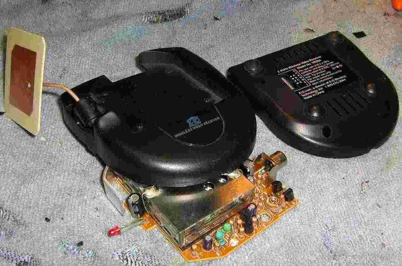
Note that the stock antenna is just a simple little patch antenna.
Internal view of the X10 VR36A receiver.
The power LED is on the left. The actual 2.4 GHz video receiver module is the silver box in the middle. The +9 VDC power input is via the connector on the top-right. The video output signal is via the RCA jack on the bottom-right.
The 2.4 GHz video receiver module only has four main connections. The 2.4 GHz antenna input (via the coax connection on the upper-left), +5 VDC for power, baseband video out, and ground.
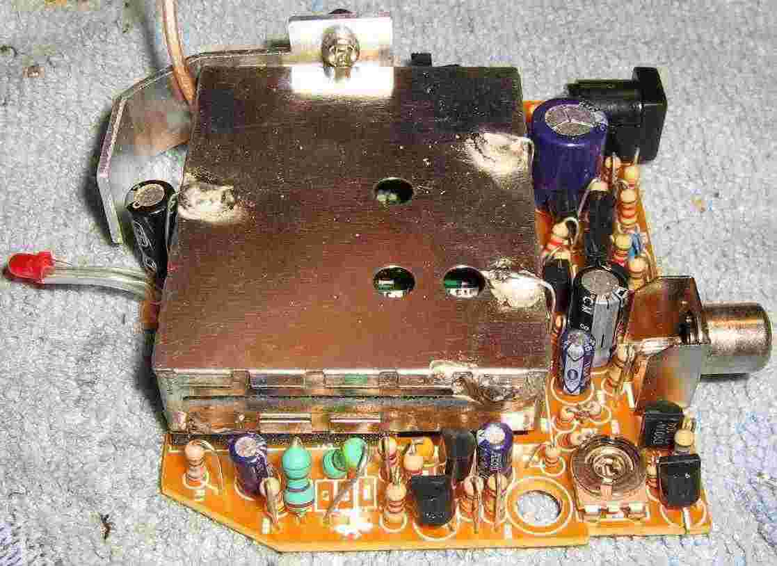
Underside view of the X10 VR36A receiver.
+9 VDC power input is on the lower-left, and the video output is on the lower-right.
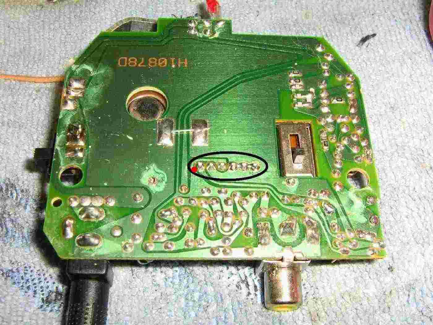
The 4-position "Channel Select" switch is on the right-side. The switch is in the "Channel A" position.
The six pins circled are the connections to the actual 2.4 GHz video receiver module.
Four of them are ground, one is +5 VDC, and one (red dot) is the baseband video output.
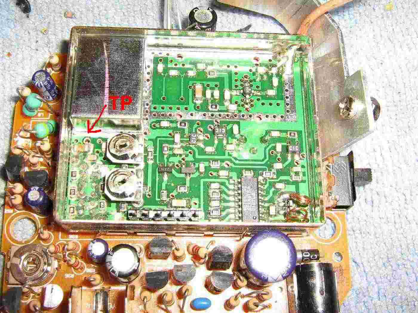
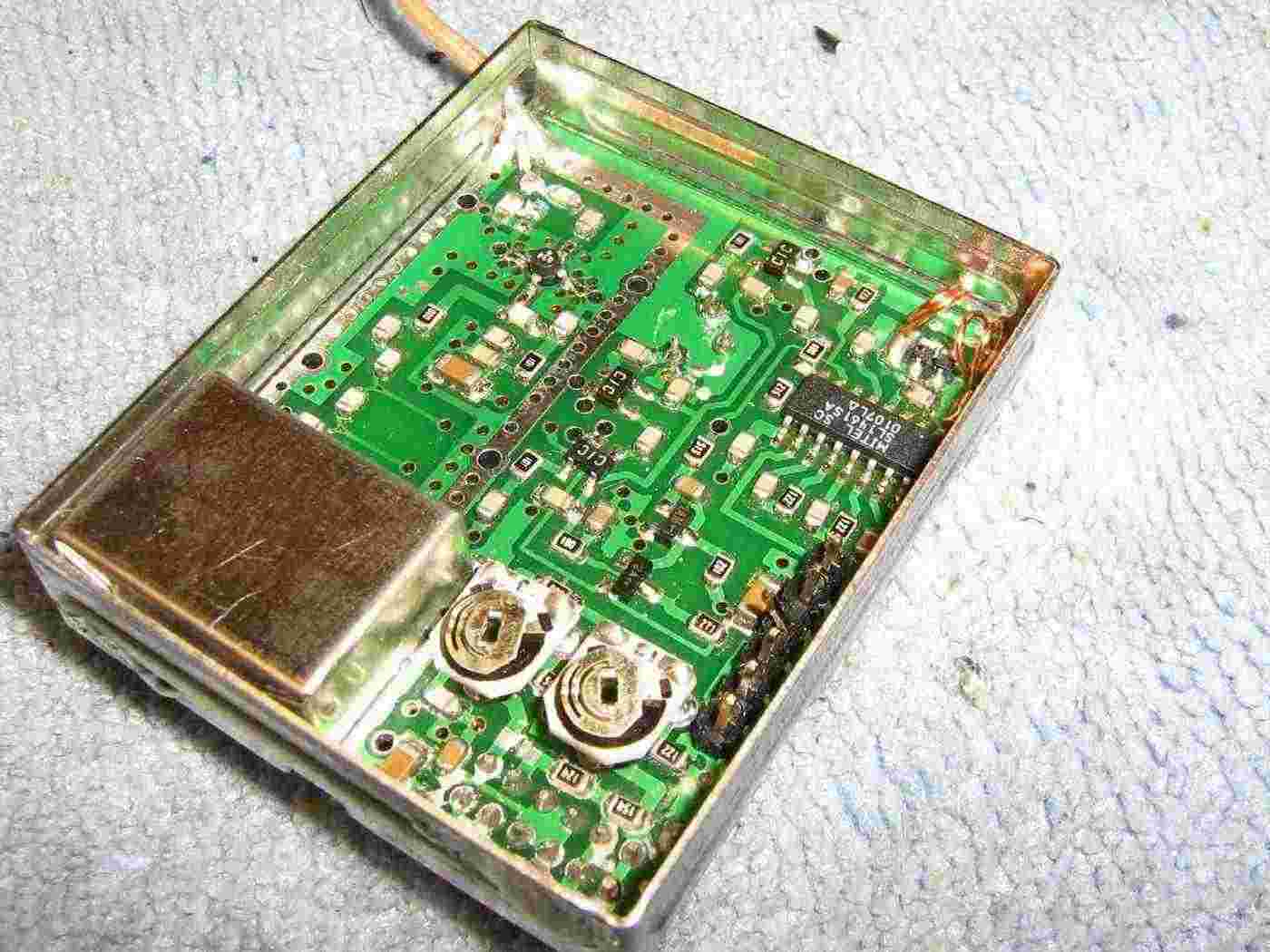
Overview of the 2.4 GHz video receiver module.
The antenna input is via the piece of coax on the upper-right. It is amplified around 16 dB using a Sirenza SGA-3486 MMIC and then high-pass filtered before entering the shielded mixer/local oscillator section. This module, and most others, use an IF output frequency of 480 MHz and a low-side local oscillator. This means to receive a video signal at 2.45 GHz, the local oscillator needs to be set to 1.97 GHz.
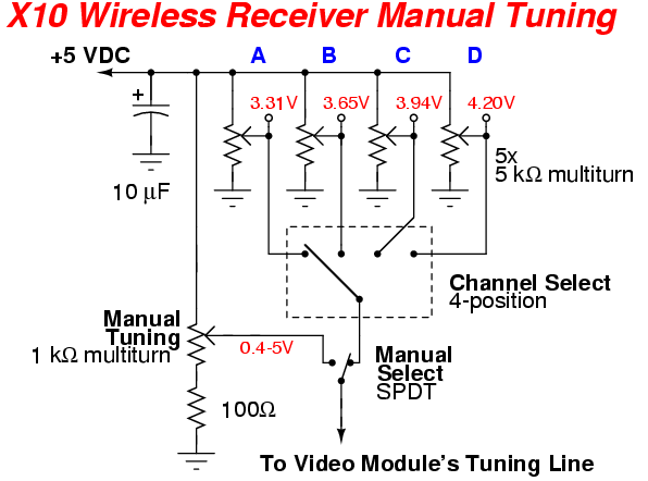
This is where the "Channel Select" switch comes into play. As you can see in the above photo, the switch is used to select between four different resistive voltage dividers which determine the voltage on the local oscillator's tuning line. The two potentiometers appear to be "fine tune" controls for this voltage. The "TP Voltages" in the chart at the beginning of this article where taken at the plated through-hole labeled TP in the above photo.
The idea is that by manually adjusting the voltage on this local oscillator tuning line, we can then make the module receive "out-of-band" video signals.
Alternate internal view of the 2.4 GHz video receiver module.
You'll need to remove the 2.4 GHz video receiver module to perform the next modifications.
This is a little better view of the voltage-dividing resistors and the "Channel Select" switch pin-out.
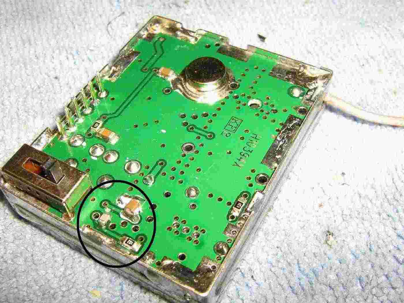
Bottom view of the 2.4 GHz video receiver module.
The circled portion is the voltage tuning line input for the mixer/local oscillator section.
A series 1,000 ohm resistor and shunt capacitor help to form a low-pass filter to remove any noise on the tuning line.
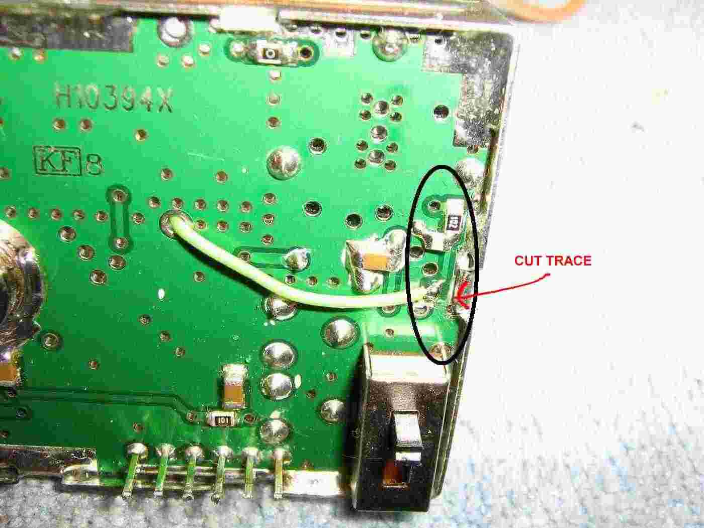
Overview of the manual tuning modification.
You'll need to cut the trace on the voltage tuning line (right after the plated through-hole) and move the shunt capacitor next to the 1,000 ohm resistor.
Then you'll solder an extension wire onto this "new" voltage tuning line and route it to the top of the board.
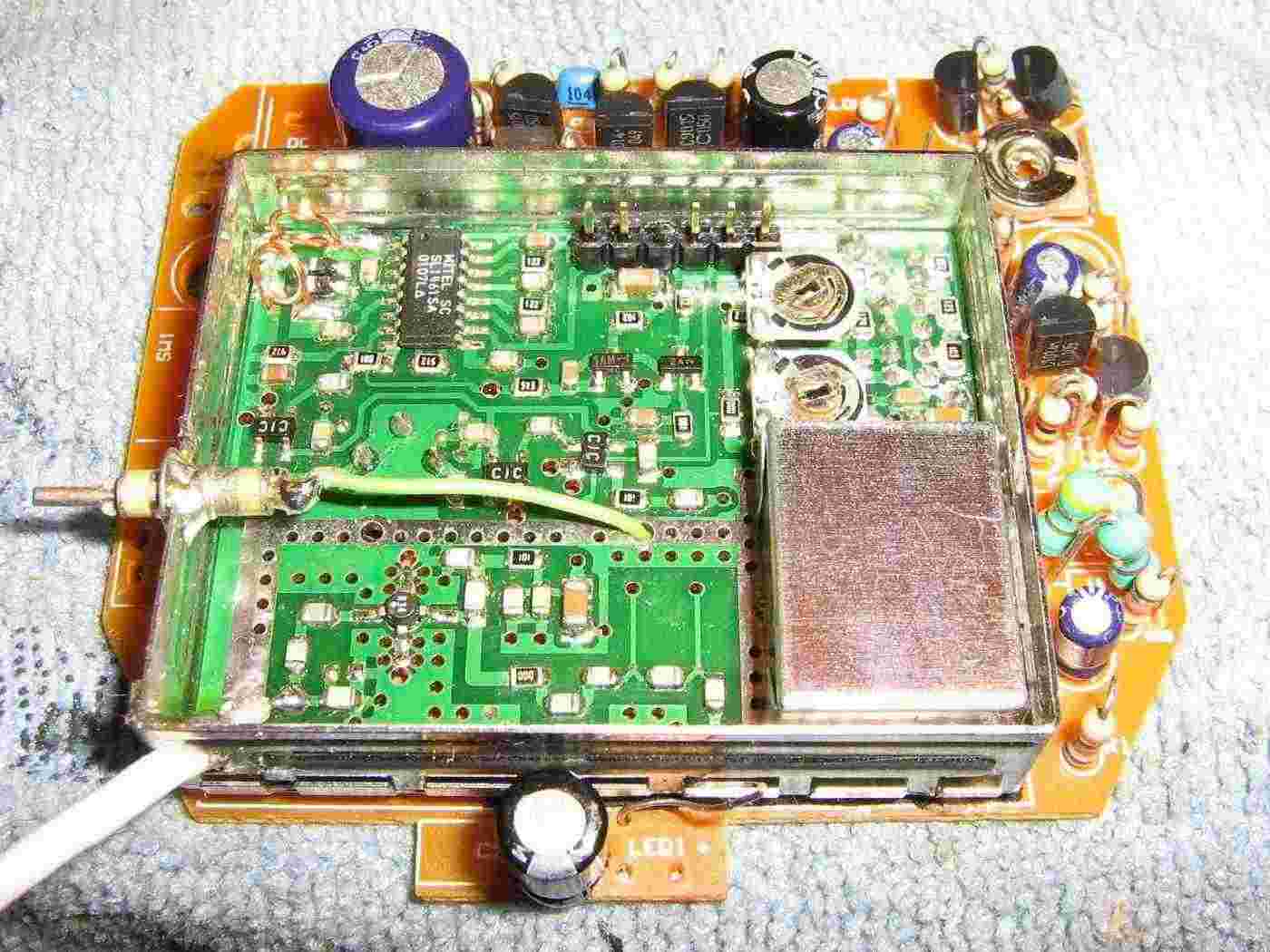
Overview of the "new" external voltage tuning line.
I ran it to a panel-mounted 1,000 pF feed-through capacitor. This capacitor is optional, but very helpful.
Also, you may wish to add a better piece of coax on the module's RF input. I added a piece of nice Teflon coax with a male SMA connector.
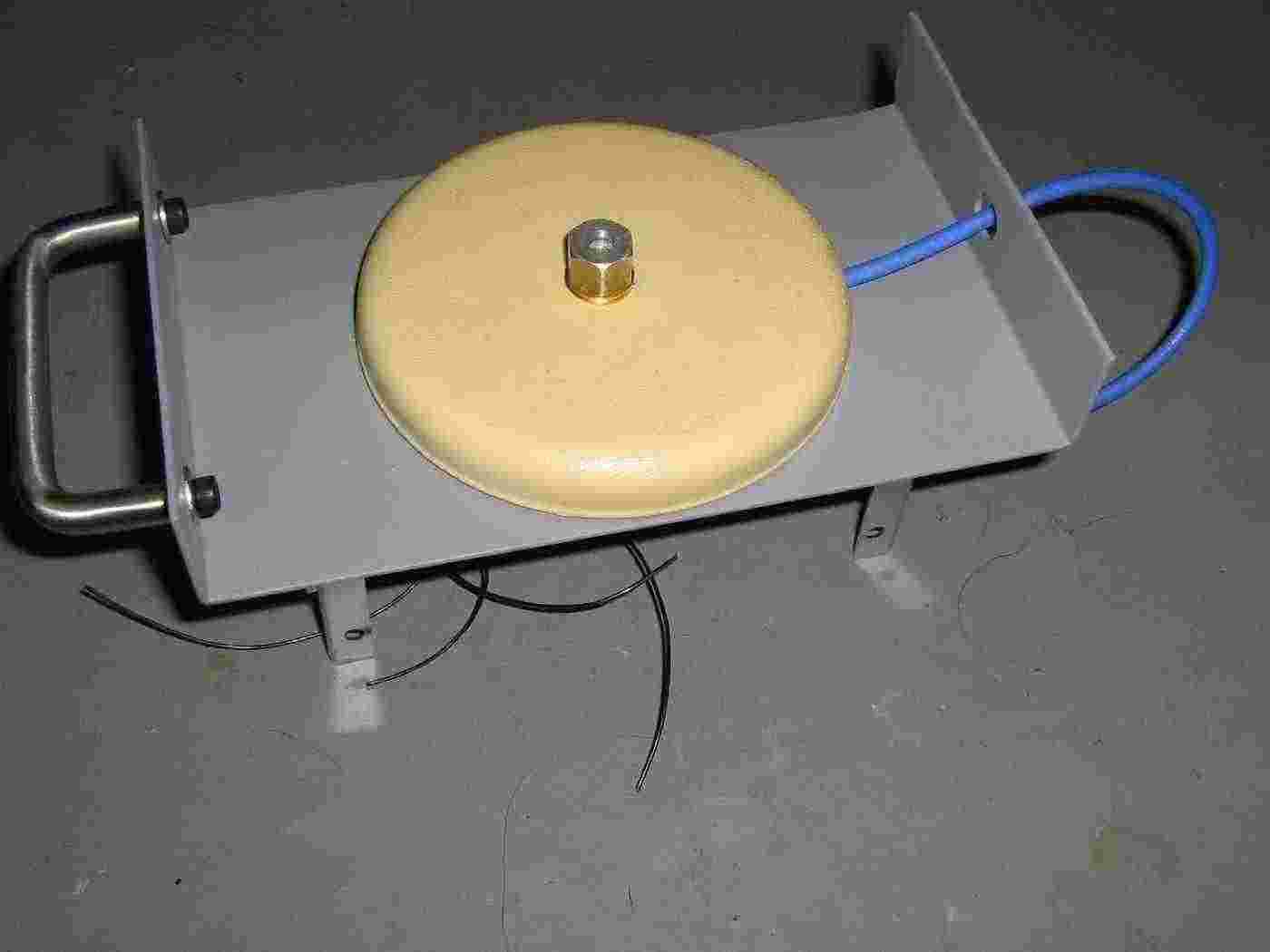
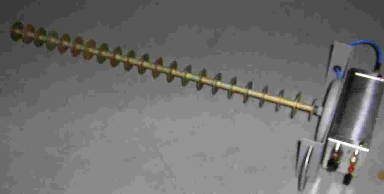
For this project, we'll mount the 2.4 GHz video receiver to the back of an old California Amplifier 2.5 GHz MMDS integrated downconverter and 22-element Yagi antenna.
You'll want to replace the stock coax on the Yagi with something of higher quality and with a RF connector. This will allow you to use the antenna for other projects, if so needed.
A handle was also added to the back plate of the Yagi antenna for mounting or holding.
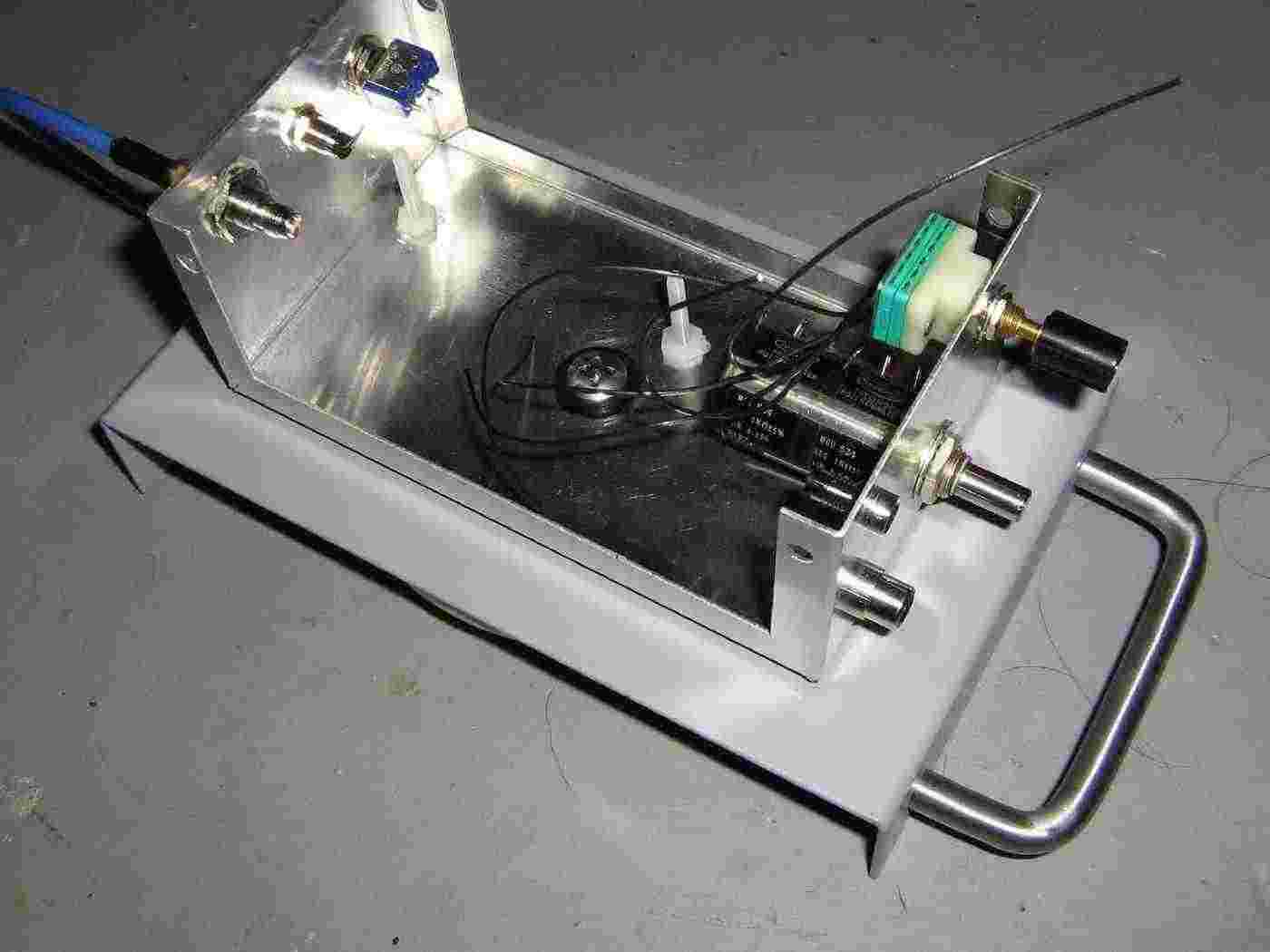
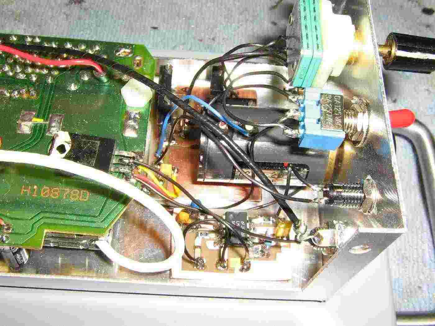
Case overview used to hold the modified VR36A receiver.
The stock downconverter was removed and a stainless steel 1/4-20 bolt was added to secure both the antenna parts and the aluminum project case. The circuit board of the VR36A will be mounted to the case using some nylon stand-offs and hardware.
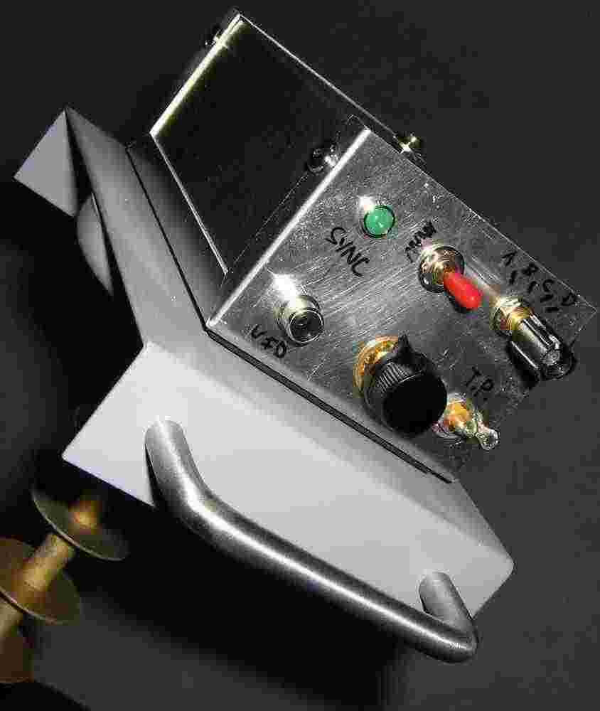
A panel-mount, feed-through female SMA-to-SMA connector is used to bring the RF signal into the module. Next to that is a panel-mounted LED and the power switch.
The panel-mount switch with the green back is a 4-position switch. Next to the switch is a multiturn 1,000 ohm potetiometer, and a RCA jack for the video output.
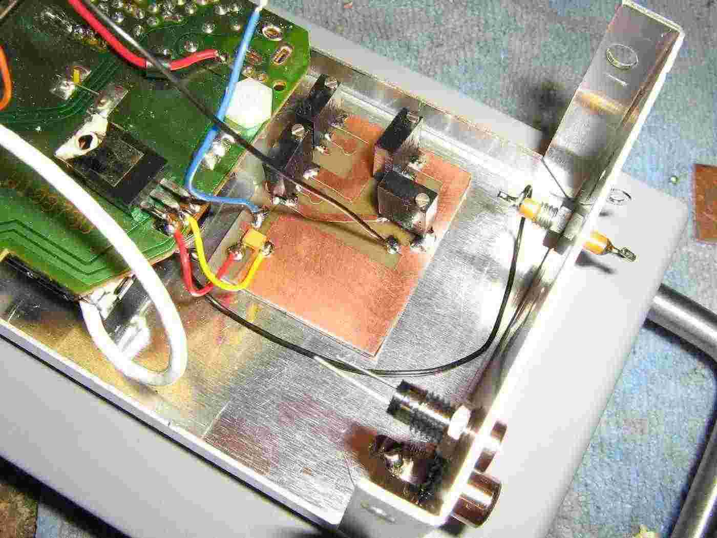
Overview of the potentiometers for setting the voltage levels which correspond to each of the four stock channels.
An optional feed-through capacitor (upper-right) was added as a test point to externally monitor the voltage on the module's tuning line.
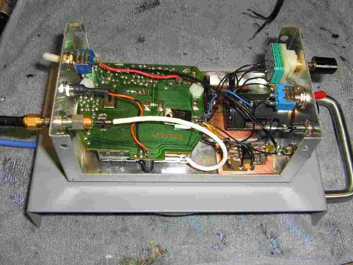
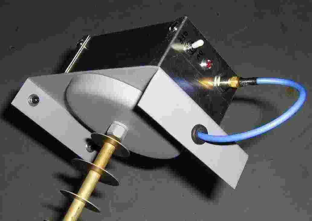
Completed 'warspying' device overview.
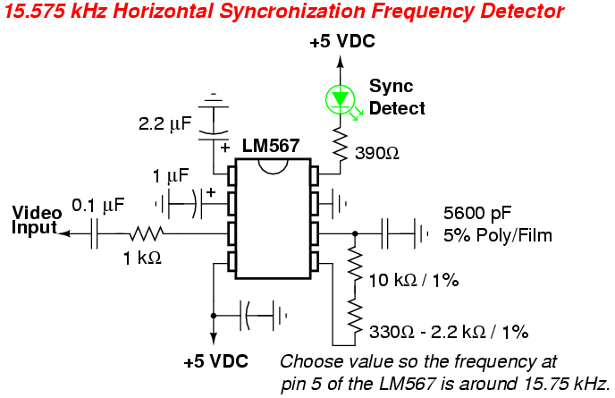
An optional 15.75 kHz horizontal synchronization detector circuit using a LM567 tone decoder was added to help determine if you are actually receiving a video signal.
You should also try and replace the stock 7805 voltage regulator with one which has better noise and voltage stability specifications.
Closeup view.
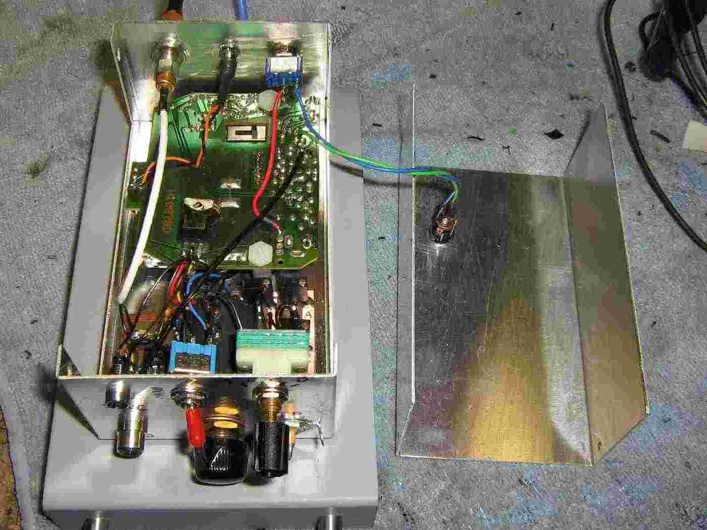
Alternate internal view.
Originally, I was going to use an internally-mounted 9 volt battery, but the current draw is quite high, 300 mA or so, and the battery would die quickly.
An external power jack was added to run the circuit from a 12 volt lead-acid battery pack or cigarette lighter.
Finished case overview.
Power switch, power LED, and SMA jack for RF input.
Finished case overview.
Video output and 15.75 kHz horizontal synchronization detection LED on the left.
Selector switch to choose between the four stock channels and manual tuning. The multiturn 1,000 ohm manual tuning potentiometer is in the middle.
The new 4-position channel select switch and the tuning voltage test point are on the right.
Finished overview.
The video output can be monitored via a battery-powered TV, or other monitor, with a "video input" jack.
The Portable Video Camera Viewer project discussed in GBPPR 'Zine, Issue #22 will also work.
"A" is the default channel for the corresponding X10 transmitters.