Building a DTMF Decoder
by B/Square and Mr. Upsetter
Imagine this scenario: you are listening to your scanner, monitoring a neighbor using his cordless phone. He is accessing his bank-by-phone account. He enters his password, and you hear the whole thing. But the only problem is that he entered the password using Touch-Tones. How do you know which numbers he entered?
Or think of this: you're doing an investigation and recording telephone calls. The person under surveillance is making calls with a Touch-Tone phone and you have tapes of everything. But how do you find out what numbers were dialed?
One answer to these problems would be to buy a commercial DTMF (Touch-Tone) decoder or a similar device called a pen register. These items could cost you a few hundred dollars. The other solution is to build the handy "snatch 'n latch" DTMF decoder presented here for about $35 to $45.
This circuit uses a single chip to decode 12 or all 16 DTMF tones, as selected by the user. Up to 16 tones are stored in the circuit's static RAM memory. Once the tones are in memory, the user reads them out one by one on the circuit's LED display. The circuit can be hooked up to a telephone line, a scanner, or a tape recorder. Now let's take a look at how this little device works.
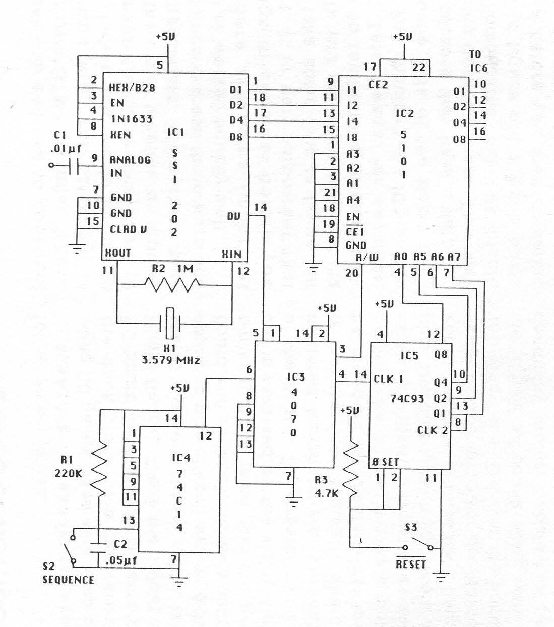
Theory of Operation
DTMF signals are coupled to pin-9 of IC1, the DTMF decoder chip, by .01 µF capacitor C1. The tones are band-split sampled and a coded output is placed on D1, D2, D4, D8, of IC1. Data Valid (pin-14) goes high 7 µs after data is on bus causing the R/W input of the RAM, IC2, to go low and the CLK1 input (pin-14) of the counter, IC5, to go high by way of IC3, the XOR.
At this time, the digit received is displayed on LED1 while preconditions (to write the data to memory) are established.
45 ms after the tone ends, Data Valid goes low, writing the data into RAM and incrementing the counter one count. Code has been written into address 00 of the RAM with the next address presented to A0, A5, A6, A7 of the RAM.
4.56 ms after Data Valid goes low, the outputs D1, D2, D4, D8 of the decoder clear. This sequence will continue until addresses 00 through 15 contain data. At this time, the counter recycles and data will be written over what was previously stored.
To read out the contents of memory, RESET (S3) is opened, causing pin-1 and pin-2 of the counter to go high. This resets the counter address bus to 00.
The data in address 00 of the RAM is presented to IC6, the BCD to 7-segment driver. IC6 converts the RAM output data to a digit which is read out on LED1.
When SEQUENCE (S2) is closed, pin-12 of IC4, the Schmitt trigger, goes high. This causes pin-14 of the counter to go from low to high by way of the XOR. This increments the counter and presents the next address to the RAM, and the next digit is read out.
S2 is repeatedly pressed until all the contents of memory have been displayed.

Circuit Construction
There are two different techniques you can use to construct your own DTMF decoder. These are wire wrap and soldering. In fact, before you decide to build a permanent unit, you may want to put the circuit together on a plastic breadboard. The authors have built units in these three ways and they all worked equally well.
There are some important things to consider before you start. It is very important that you take some time to figure out where you are going to place the ICs to facilitate a "clean" project. This means, for example, that you shouldn't put IC1 on the opposite side of the board from IC2 because they have a data bus running between them.
This may get complicated, but it is important to figure out a good parts layout before you start soldering things together. Also, it is a good idea to buy all the parts, including PC board, enclosure, sockets, switches, etc. before you get started on a permanent unit so you can plan how you are going to put everything together.
In addition, unless you are a soldering whiz, it is highly recommended that you use sockets for all the ICs. This also makes troubleshooting the device and replacing ICs easier.
This project uses CMOS ICs, which are static sensitive. Theoretically you and your soldering iron should be grounded when handling the ICs. If you don't have an anti-static workstation handy, don't worry about it too much. Try not to touch the pins of the ICs and store them in conductive foam or a piece of tin foil when not in use.
Assembly is readily achieved using 30 gauge hand wire wrap on the back plane of a "universal" PC board (available from Jameco, RadioShack). Once the layout of the ICs is determined, solder two opposing pins of each socket to the board and methodically wire pin to pin keeping in mind that the pin-out is reversed on the wiring side of the board.
The crystal can be mounted horizontally or vertically, but the 7805 regulator should be mounted horizontally for low profile. The 30 gauge wire is soldered directly to the switches and jack. Double-checking your work at various stages will assure a functional device at power-up.
Before you insert the ICs into the sockets, check all connections with a continuity meter. Should the circuit not operate, suspect your work before questioning the ICs. The advantage of wire wrap is that it is easier to correct your mistakes.
Assembly by soldering is quite similar to wire wrap. A board with a pattern such as RadioShack Part No. 276-162 is recommended. Solder the IC sockets to the board once you decide on a good layout. Solder the other parts in place. Solder small gauge wires from pin to pin on the component side of the board. Use small jumpers made from component leads for short connections on the component side and the solder side. Check all connections with a continuity meter.
When you put the ICs in their sockets, remember to put them in the correct way, not backwards.
As good circuit design practice you may want to put 0.1 µF capacitors between the power supply pins of each IC and ground. The device will work without them, however.
After you are done with the PCB, think about where you are going to put the LED display, input jack, and switches on your enclosure. Assembly and disassembly will be easier if all of these things are attached to one-half of your box.
Using the Decoder
Using the "snatch 'n latch" isn't too hard, but there are a few details about its operation that we need to observe.
When you first turn the unit on, be sure to hit the reset switch. This ensures that the tones (or rather the data sent from the decoder to memory) will be stored in the first memory location.
Then you sit back and wait for some DTMF tones to come down the line. When they do, the device will snatch 'em and stash 'em in the memory. When the tones have stopped, hit the RESET switch. You will see a number on the display, which is the number stored in the first memory location.
Hit the SEQUENCE button and the numbers in the subsequent memory locations will be read out. Once you've read out all the numbers and written them down somewhere, hit the RESET switch again. You are ready to start all over again.
The numbers will be in memory as long as the power is on and new numbers haven't been written over the old ones. (That's why you may want to write down the numbers, because any new numbers that come in will erase the old ones.)
There are a few other helpful hints that can make using the decoder easier. First of all, install that switch to turn the LED display on and off. You only need the display when you're reading out numbers, and switching it off will prolong battery life. Also, while reading out the numbers, you might want to remove the device from the phone line or whatever it is hooked up to. If the decoder happens to receive a tone while you're reading out the numbers in memory, the tone will be stored in whatever memory location you happen to be at and generally make things confusing.
One feature of the "snatch 'n latch" that makes it less attractive than commercial models is that it can only store 16 tones. If more than 16 tones are read by the decoder, the counter resets the RAM to the first memory location and the excess tones are read into memory, erasing the previous ones. This is a problem since information is lost. If you anticipate reading in more than 16 tones at one time, you can record the tones on tape and play them back a few at a time into the decoder.
When using the decoder with a tape recorder, hook it up to the earphone jack and adjust the volume so the decoder will read the tones off the tape. The decoder isn't terribly picky about input levels, but theoretically the input level should be less than the supply voltage, which is 5 volts DC. When using the decoder with a scanner, it's best to hook it up to a "Tape Out" jack if it has one.
Otherwise you can hook it up to the earphone jack. The decoder works like a charm when hooked up directly to a phone line (parallel connected), as the capacitor on the input of the DTMF decoder IC blocks the phone line's DC voltage. However, if you are going to hook up the "snatch 'n latch" to the phone line for any extended period of time, circuitry must be added to the input to protect the device from the ringing voltage. 90 volts AC on the line will surely wreak havoc on the CMOS ICs.
Applications
The DTMF decoder has many interesting uses. Basically, anytime you hear a tone and want to know what it is, hook up the decoder and let it go to work. When it is hooked up to a phone line, the number dialed can be decoded. You can also decode DTMF tones (e.g. passwords) used for services like bank-by-phone, credit card verification, voice mail systems, etc. Calling card numbers can be obtained in the same way if they are entered by Touch-Tone. If you monitor cordless or cellular phones with a scanner, you can hear a lot of this type of DTMF tone use. With a scanner you can also decode such things as access tones for repeaters. DTMF signaling is so widespread there's no doubt that you will discover other useful applications.
The "snatch 'n latch" DTMF decoder presented here is a cost-effective circuit that is an invaluable tool for the telephone experimenter. We hope this article will start you on your way towards building your own.
Parts List
C1 = 0.01 µF C2 = 0.05 µF R1 = 220 kΩ, 1/4 watt R2 = 1 MΩ, 1/4 watt R3 = 4.7 kΩ, 1/4 watt RN1 = 470Ω X1 = 3.579 MHz Colorburst Crystal, HC-18 case S1 = SPST Switch S2 = SPST Momentary, normally-open S3 = SPST momentary, normally-closed S4 = SPST Switch IC1 = Silicon Systems SSI202 DTMF Decoder IC2 = Intel 5101, 1024-bit (256x4) Static RAM IC3 = CD4070, quad XOR 1C4 = 74C14, hex Schmitt trigger IC5 = 74C93, ripple counter IC6 = 74C48, BCD to 7-segment IC7 = 7805, 5V regulator LED1 = 7-Segment, common-cathode Miscellaneous Parts: * 1/8-inch jack * IC sockets * PC board * 9V battery and clip * 0.1 µF capacitors * Enclosure * Mounting Hardware |
All of the ICs except for IC1 are available from:
Jameco Electronics 1355 Shoreway Road Belmont, CA 94002 (415) 592-8097 |
They also have sockets, the crystal, and other parts. Some parts are also available from Mouser Electronics. Call 800-992-9943 for a free catalog.
The Silicon Systems SSI202 DTMF decoder IC is available from:
W.E.B. PO Box 2771 Spring Valley, CA 92077 $12.95 + $2.50 postage and handling. |