This is a RF jammer designed for the U.S. 800 MHz cellular phone band (870-895 MHz). It works by generating an overpowering sweeping RF carrier on the cellular handset's receive frequency range.
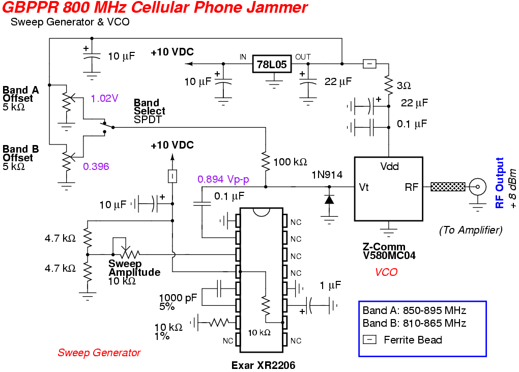
An Exar XR2206 Multifunction Generator will be used as the triangle wave generator for providing the sweep portion of the jammer circuit. The sweep generator will control a Z-Communications V580MC04 Voltage Controlled Oscillator (VCO) to sweep between approximately 850-895 MHz at a rate of around 100 kHz.
The VCO is arguably the most important component in a cellular phone jamming system. It's a little four-terminal device (Vcc, RF Output, Voltage Tune, and Ground) which generates the required low-level RF output signal with a minimal amount of fuss. Unfortunately, VCOs covering the proper frequency range you need can be difficult to find. Companies such as Mini-Circuits and Z-Communications are very helpful to amateur electronics enthusiasts, and will sell their VCO models in single quantities directly or point you to a local distributor.
The VCO you choose should cover the frequency range of the cellular base station's downlink frequencies (tower transmit) you wish to jam. You always try to jam the receiver, so in this case, you'd jam the mobile station's (handset) receive frequencies - which are the cellular tower's transmit frequencies. These frequencies will vary around the world, but the overall concept will remain the same.
  Technology        General Frequency Range (MHz)

  3G CDMA           869 - 894  (TX: 824 - 849 / 896 - 901)
  GSM 900           925 - 960  (TX: 880 - 915)
  Verizon 4G LTE    746 - 757  (TX: 776 - 787)
  AT&T 4G LTE       698 - 716  (TX: 728 - 746)
  4G LTE            728 - 768  (TX: 698 - 716 / 777 - 787 / 788 - 798)
  DCS               1805 - 1880  (TX: 1710 - 1785)
  3G PCS            1930 - 1990  (TX: 1850 - 1910)
  3G                2110 - 2170  (TX: 1920-1980)
  4G WiMAX          2345 - 2400 / 2620 - 2690
  Globalstar        2484 - 2500  (TX: 1610 - 1626)
  802.11b WiFi      2400 - 2500
  L1 GPS            1575.42
  L2 GPS            1227.60
  L5 GPS            1176.45
Two 5 kohm multiturn potentiometers are required to provide a proper DC offset for the VCO's voltage tune line. What this does is give the sweeping triangle wave a positive DC voltage offset to help "center" the sweeping triangle wave within the required jamming frequency range. The amplitude of the triangle wave corresponds directly to the frequency width of the jamming range. Here's an example using a generic VCO:
  Voltage Tune (+ Volts DC)      Frequency Output (MHz)

  0                              790
  1                              810
  2                              830
  3                              850
  4                              870
  5                              890
  6                              910
In our above example, a particular VCO is capable of tuning between 790-910 MHz with a voltage tune from 0 to +6 VDC. This works out to about 20 MHz of tuning per volt. So, if a person wanted to "jam" the frequencies between 870-890 MHz, they would need a +1 volt peak-to-peak triangle wave with a DC offset of +4 volts. This would result in voltage signal sweeping between +4 and +5 VDC (referenced from ground), and would sweep the VCO's RF output between 870-890 MHz. Of course, in real life, the voltage-to-frequency mappings are not this precise.
Another important section of the RF jammer chain is the final RF power amplifier. This is a device which takes a small RF input signal, say at +10 dBm (10 milliwatts), and amplifies it up to around +36 dBm (4 watts) or more. The cheapest source of these amplifiers is from old analog cellular phones themselves. Some older cellular phones (Motorola, Nokia, Uniden, etc.) will use a broadband RF power "hybrid" module which helps make their construction easier and smaller.
These RF module devices tend to be very wideband frequency wise, and will easily amplify RF signals outside of their intended range. Increasing the module's RF power control bias (Vapc) or Vdd voltage can also milk a little more gain out of them, but will also negatively effect the lifetime of the power module. The RF power module will need to be connected to a large, smooth heatsink and may also require a cooling fan on higher power amplifiers.
For this project, we'll be using a Hitachi PF0030 820-850 MHz RF power amplifier module salvaged from an old CT-1055 Radio Shack/Nokia cellular phone. These particular modules will work to over 900 MHz with only a slight decrease in gain at those higher frequencies. Running the Vdd voltage at +15 to +17 VDC will also slightly increases the available RF power output. I've gotten them to hit 10+ watts output when properly layed out and constructed with a large heatsink, but it's usually not worth the risk. Try to keep the maximum RF output power around 4 to 6 watts.
Most broadband RF power hybrid modules rarely need more than +13 dBm (20 mW) of RF input to work properly. This is perfect for being driven directly from the VCO's RF output without the need for an additional RF pre-amplification stage. Increasing the RF input power will only shorten the lifetime of the power module and will have a minimal impact on output gain.
The most important part of any radio system is the antenna. Spend a good chunk of your money on the antenna system (and coaxial cable), and you'll have no problems. Use a coathanger and some alligator clips and you'll be emailing me 50 times a day saying it doesn't work.
Thankfully, you can also salvage a usable antenna from (some) old analog cellular phones. Those magnetic or trunk mount antennas work the best. Glass-mount antennas or anything "stick-on" are basically crap. Directional gain (Yagi) antennas can be used to increase the jammer's performance, but only in the direction the antenna is pointed. High-gain, omni-directional antennas are ideal for most RF jamming applications. For homebrew designs, you can scale down (or up) 900 MHz band amateur radio band antennas.
Below is the voltage-to-frequency mapping of Z-Comm V580MC04 VCO. The RF output power was around +8 dBm over the entire frequency range.
  Voltage Tune (+ Volts DC)      Frequency Output (MHz)

  0.00                           771
  0.15                           825  800 MHz Cell Phone Handset TX / SMR Repeater Input
  0.25                           832  800 MHz Cell Phone Handset TX
  0.50                           847  800 MHz Cell Phone Handset TX
  0.75                           861  800 MHz Nextel / SMR Repeater Output
  1.00                           874  800 MHz Cell Phone Handset RX
  1.25                           885  800 MHz Cell Phone Handset RX
  1.50                           897  800 MHz Cell Phone Handset RX
  1.75                           907  Part 15 / Amateur Radio
  2.00                           918  Part 15 / Amateur Radio
  2.25                           928  Part 15 / Amateur Radio / Pagers / GSM
  2.50                           938  Pagers / 900 MHz Trunked Systems / GSM
  2.75                           948  900 MHz Trunked Systems / GSM
  3.00                           957  STL Links / GSM
  3.25                           967
  3.50                           976
  3.75                           986
  4.00                           995
  4.25                           1004
  4.50                           1014
  4.75                           1023
  4.91                           1030
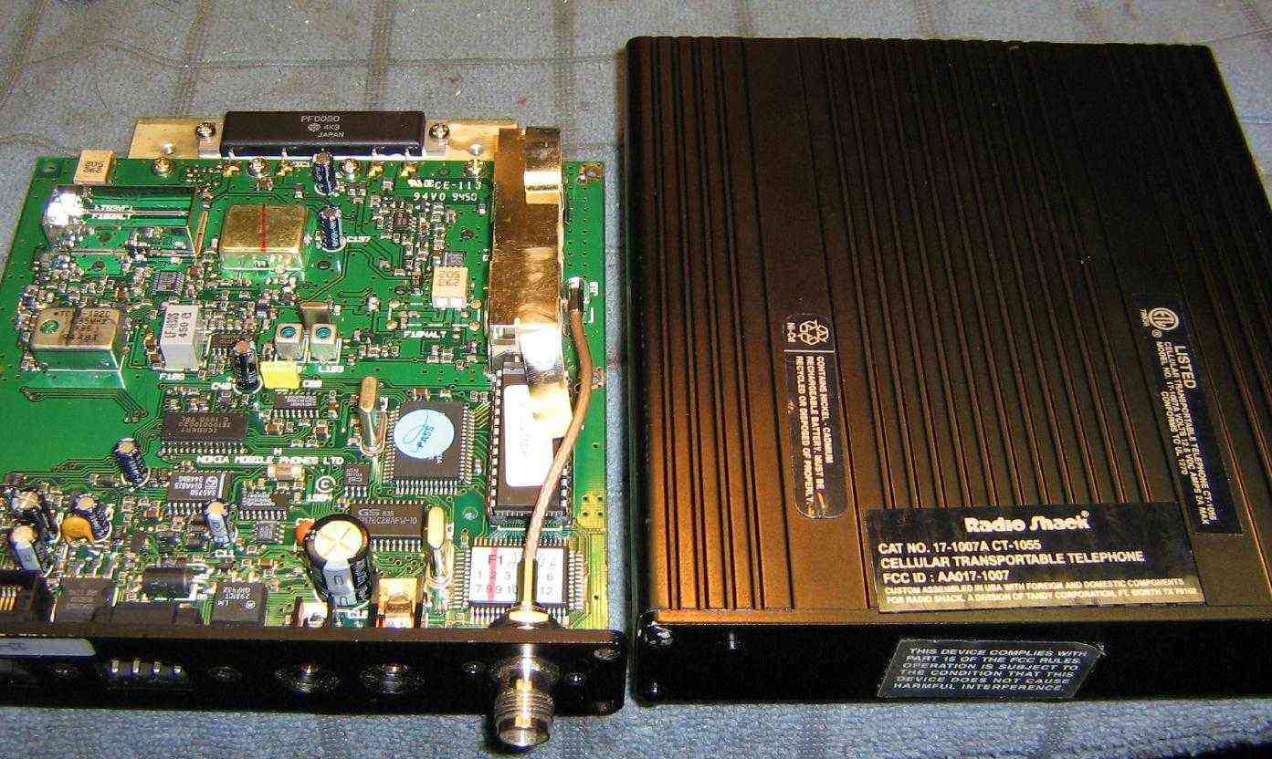
Overview of a old Radio Shack CT-1055 (Cat No. 17-1007A) 800 MHz band analog cellular phone.
The Hitachi PF0030 RF power amplifier module from this phone will be salvaged for use as the RF power amplifier in the jammer.
You can often find these cellular phones at hamradio swapfests or you can find the individual PF0030 modules on eBay for under $10.
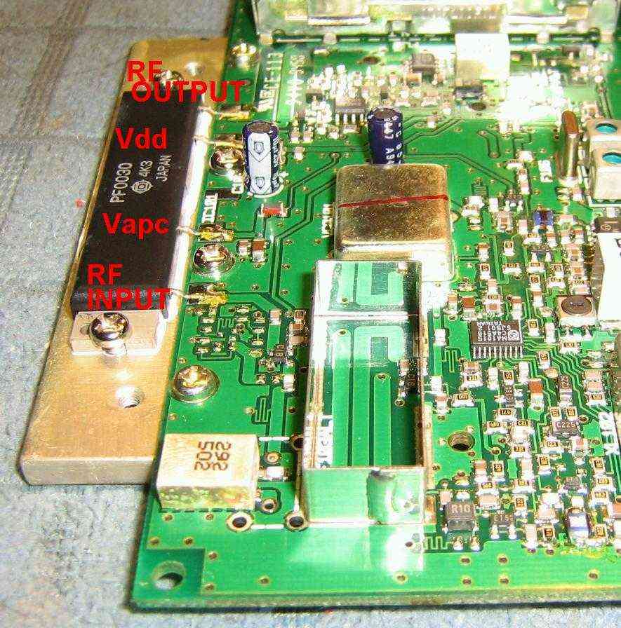
Closeup view of the Hitachi PF0030 RF power amplifier installed in the stock Radio Shack cellular phone.
Note how it is mounted on its own little aluminum heatsink block. This should also be salvaged and used in the jammer.
There should be a very thin smear of heatsink grease on the back flange of the PF0030. The PF0030 should then be attached to the heatsink via two screws. Be sure not to overtighten the screws or the PF0030's flange will flex, cracking the delicate internal circuit board.
The PF0030's flange should share a common ground with the rest of the system.
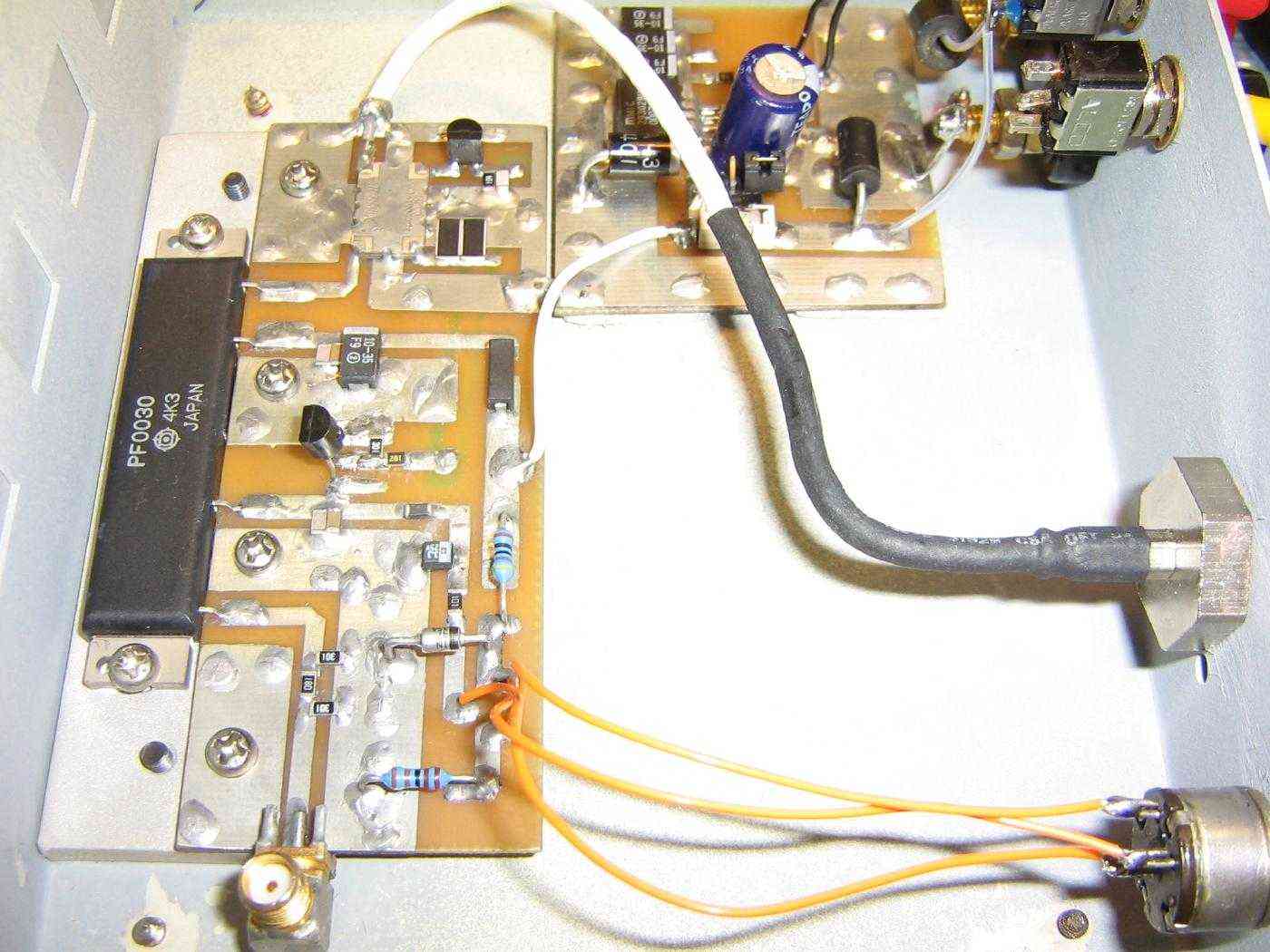
Installing the PF0030 RF power module in the case for the cellular phone jammer.
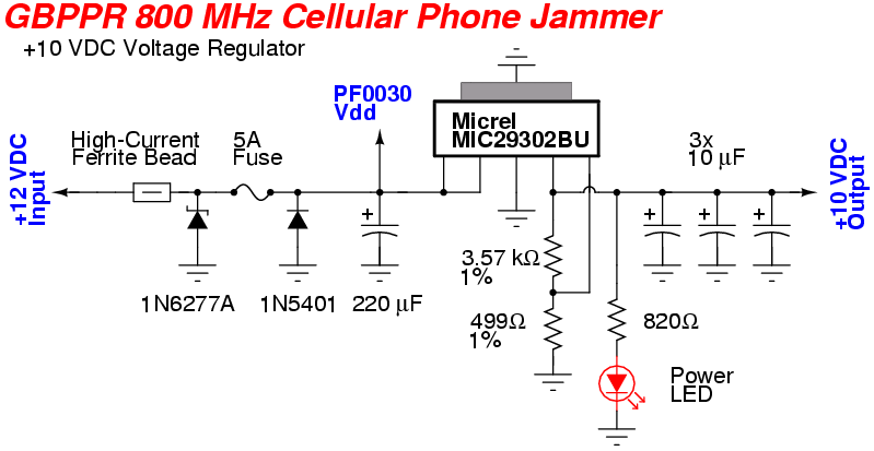
The +10 VDC voltage regulator board is mounted just behind the input banana jacks.
The regulator board is a little overengineered, but the extra filtering and protection is required if you are using the +12 VDC power from a vehicle. Those tend to be electrically noisy.
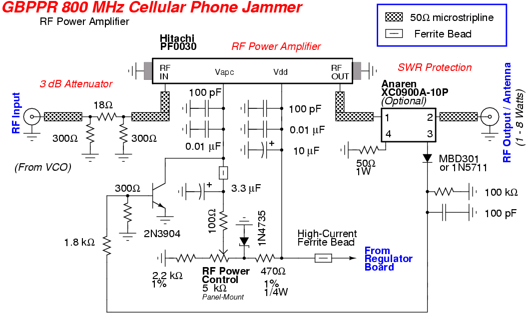
The circuit for the PF0030 is taken basically from the datasheet. An optional SWR protection circuit was added using an Anaren directional coupler to monitor the reflected power. In a high SWR condition, the voltage to the PF0030's Vapc line is shunted to ground, effectively lowering the RF output of the PF0030.
The ferrite bead on the PF0030's Vdd line should be capable of handling 3 amps continuous.
Proper RF engineering PC board layout and construction techniques should be used on the circuit board for the RF amplifier and VCO.
The PF0030's Vdd line can be connected to +10 VDC if you don't require the full RF output or if you need reduce the overall current draw.
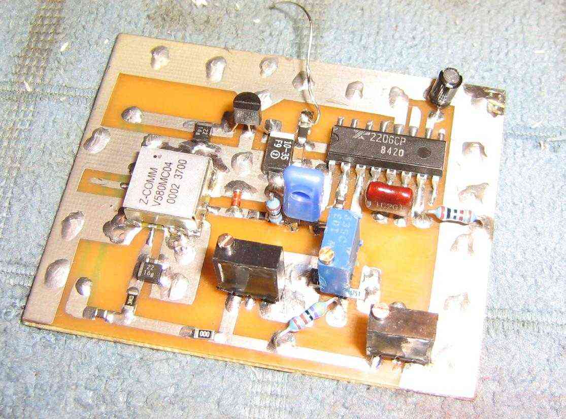
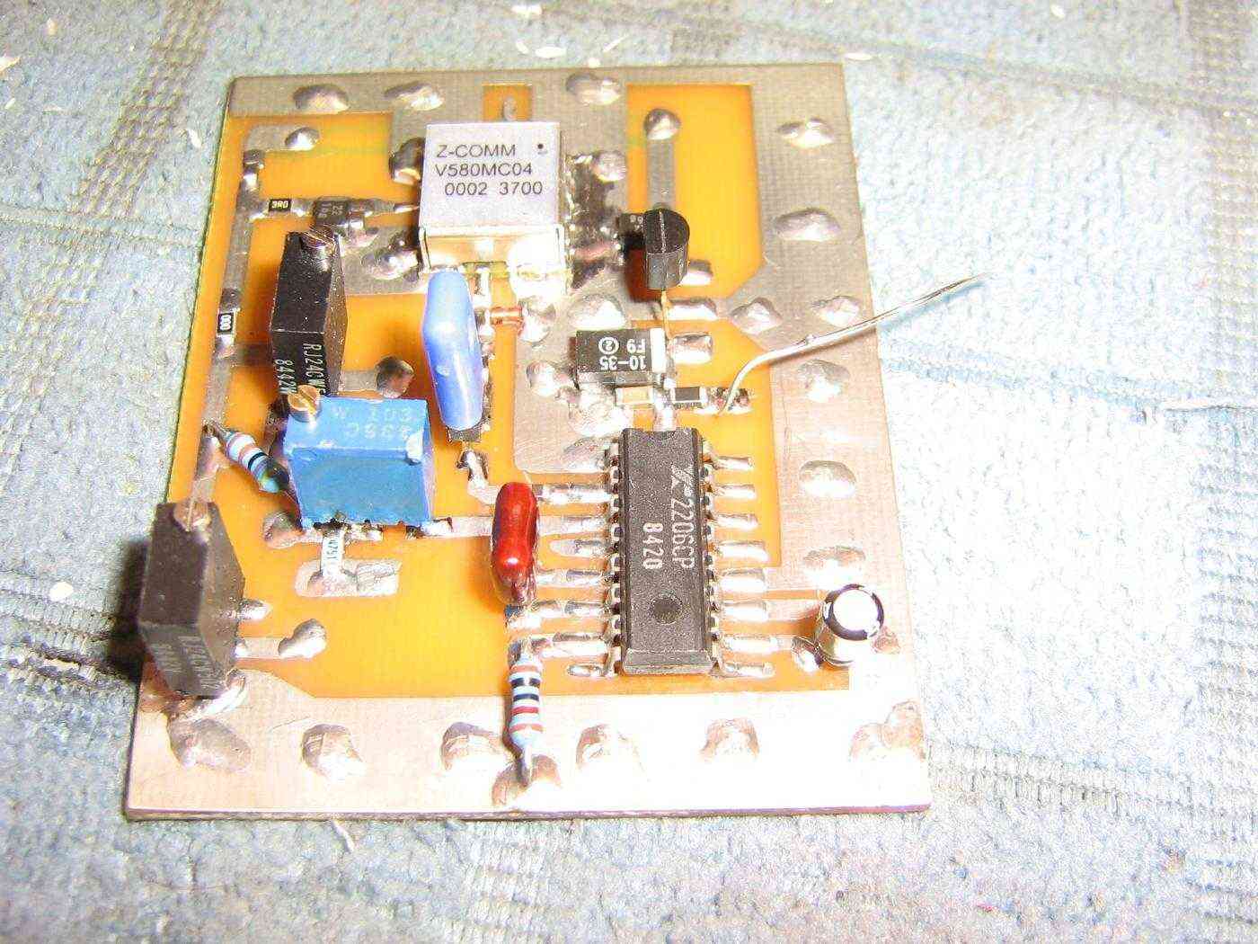
Overview of the sweep generator and VCO circuit board.
The Exar XR2206 is configured to produce a triangle wave at around 100 kHz.
The blue multiturn potentiometer controls the Sweep Amplitude of the triangle wave. This amplitude corresponds to the jammer's frequency sweep (start/stop) range.
The two black multiturn potentiometers control the Band A and Band B DC offsets on the VCO for determining the "start" frequency of the jammer.
The Z-Comm V580MC04 VCO is the silver box on the left. It has its own 78L05 voltage regulator.
Alternate view of the sweep generator and VCO circuit board.
The timing resistor and capacitor for the XR2206 should be of high quality and tolerance. A 1% tolerance 10k resistor and 5% tolerance 1000 pF capacitor are shown here.
The peak-to-peak voltage of the triangle wave should be around 0.894 volts.
The DC offset for Band A (850 - 895 MHz) should be 1.02 volts. Measured at the wiper terminal of the Band A multiturn potentiometer.
The DC offset for Band B (810 - 865 MHz) should be 0.396 volts. Measured at the wiper terminal of the Band B multiturn potentiometer.
These voltages were for my own jammer. Yours may need to be tweaked a little bit because of component tolerances. I increased the jamming frequency range on Band A a bit to cover the 800 MHz Specialized Mobile Radio (SMR), Nextel, and public safety frequencies.
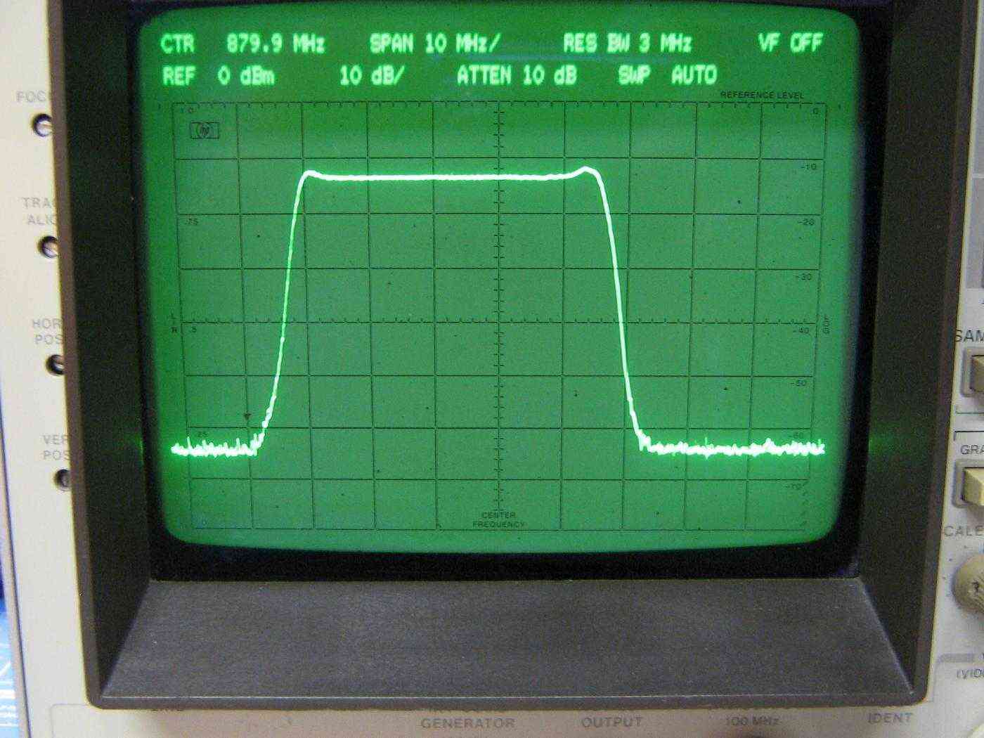
HP8569B spectrum analyzer view of the GBPPR 800 MHz Cellular Phone Jammer in operation with Band A selected.
The display is 10 MHz per horizontal division and 10 dB per vertical division.
The center frequency is 880 MHz.
The jamming frequency range is approximately 850 MHz to 895 MHz.
Because the jamming power is spread over such a large bandwidth - 45 MHz in this case - the jammer's effective range won't be as great as if were all centered on a single frequency. This is normal and should be taken into account in tactical jamming applications.
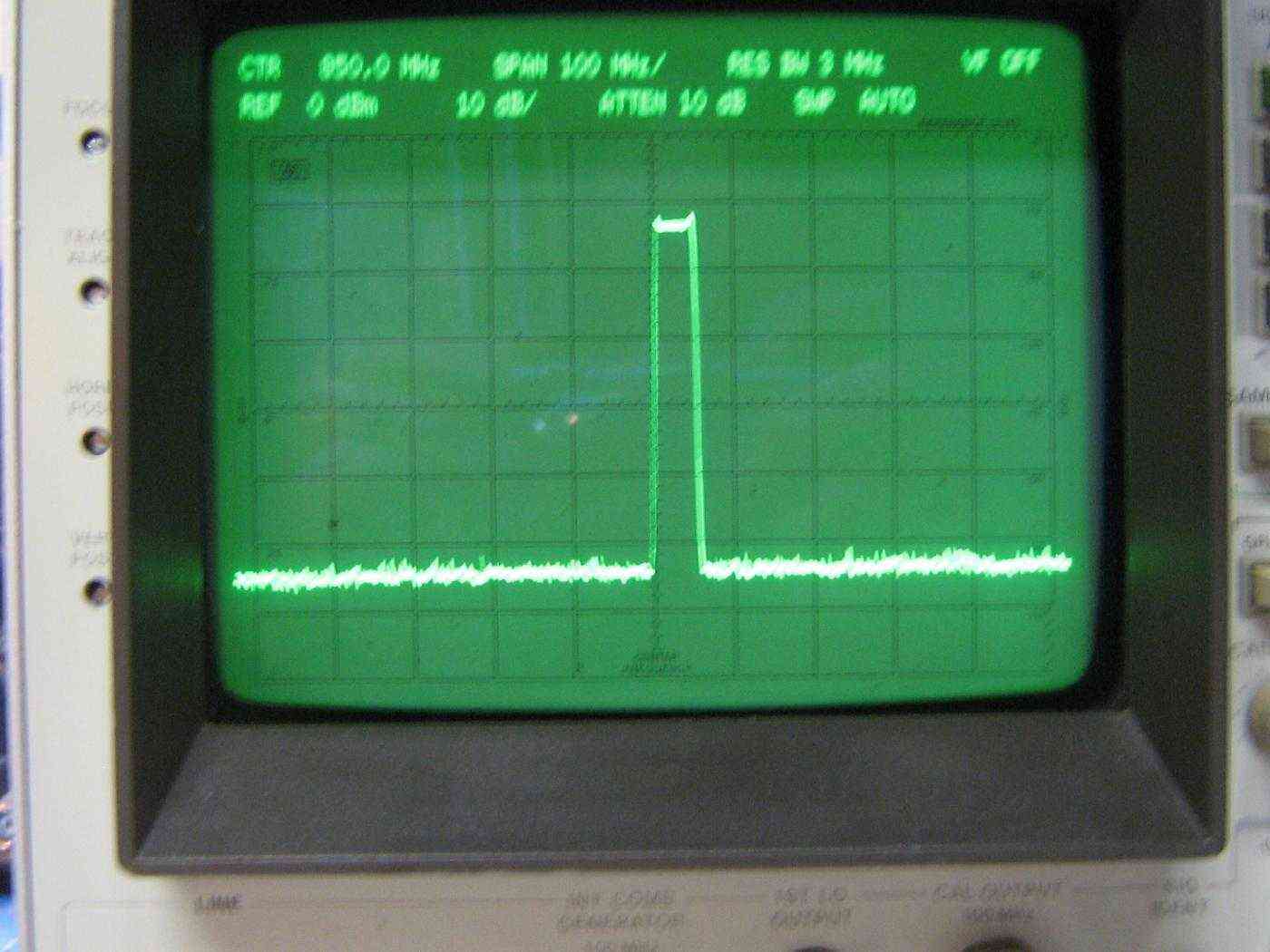
Another HP8569B spectrum analyzer view of the GBPPR 800 MHz Cellular Phone Jammer in operation with Band A selected.
The display is 100 MHz per horizontal division and 10 dB per vertical division.
The center frequency is 850 MHz.
Displayed range is 400 MHz to 1300 MHz. There were major spurs or oscillations detected in the completed jammer.
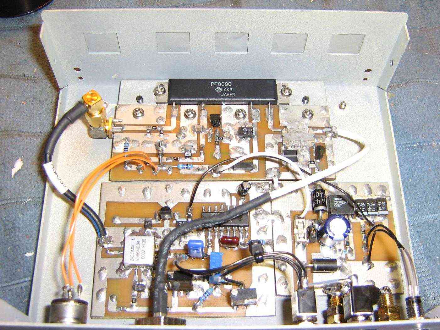
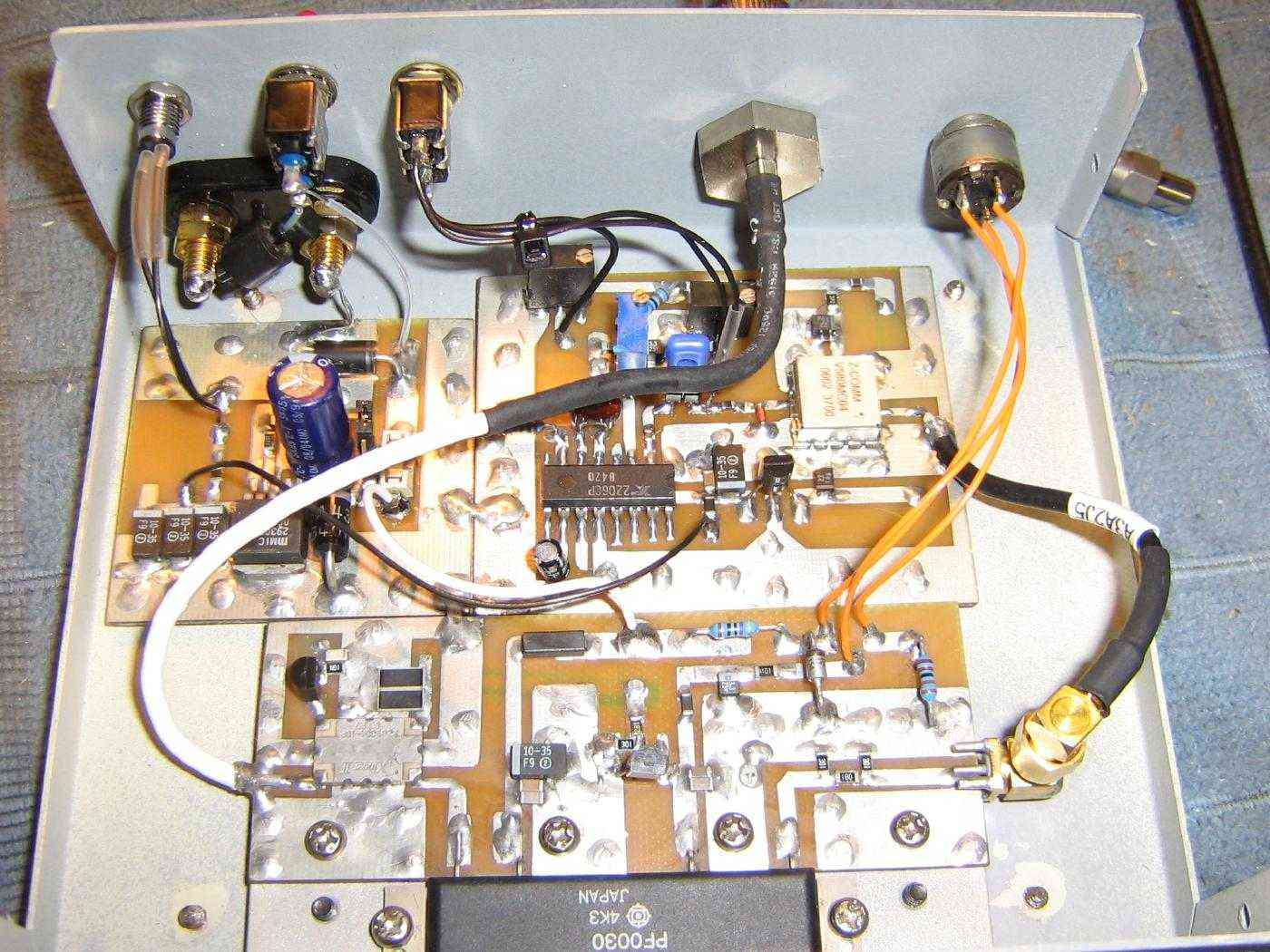
Internal overview of a completed GBPPR 800 MHz Cellular Phone Jammer.
The RF Power Control potentiometer is on the lower-left, connected via the orange wires.
The RF output from the VCO is connected to the PF0030 RF power module circuit board using a short SMA jumper.
A panel-mounted TNC connector is used for the final RF Output / Antenna connection.
Ideally, the RF output jack and the VCO shouldn't be so physically close together.
Alternate view.
The Anaren directional coupler is on the RF output of the PF0030 for an optional SWR protection circuit.
The 50 ohm termination resistor for the directional coupler should be 1 watt and of RF quality (i.e. surface mount). I didn't have any of those available, so I used two 100 ohm / 1 watt SMT resistors in parallel.
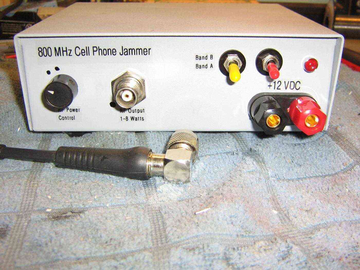
Overview of the finished GBPPR 800 MHz Cellular Phone Jammer.
An example antenna is also shown.
The RF Power Control potentiometer is on the left. Fully counter-clockwise is minimum (or no) RF output, and rotating the control clockwise gradually increases the RF output.
The RF Output / Antenna panel-mount TNC connector is in the middle.
The +12 VDC power input is via the banana jacks on the right.
The red switch is for main DC power.
The yellow switch is for Band Select.
The RF power output at +12 VDC is:
Current Draw         RF Output (dBm)      RF Output (Watts)

0.5 A                +31.7                1.48
1.0 A                +36.8                4.79
1.5 A                +38.5                7.08
2.0 A                +39.0                7.94