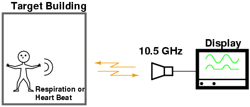
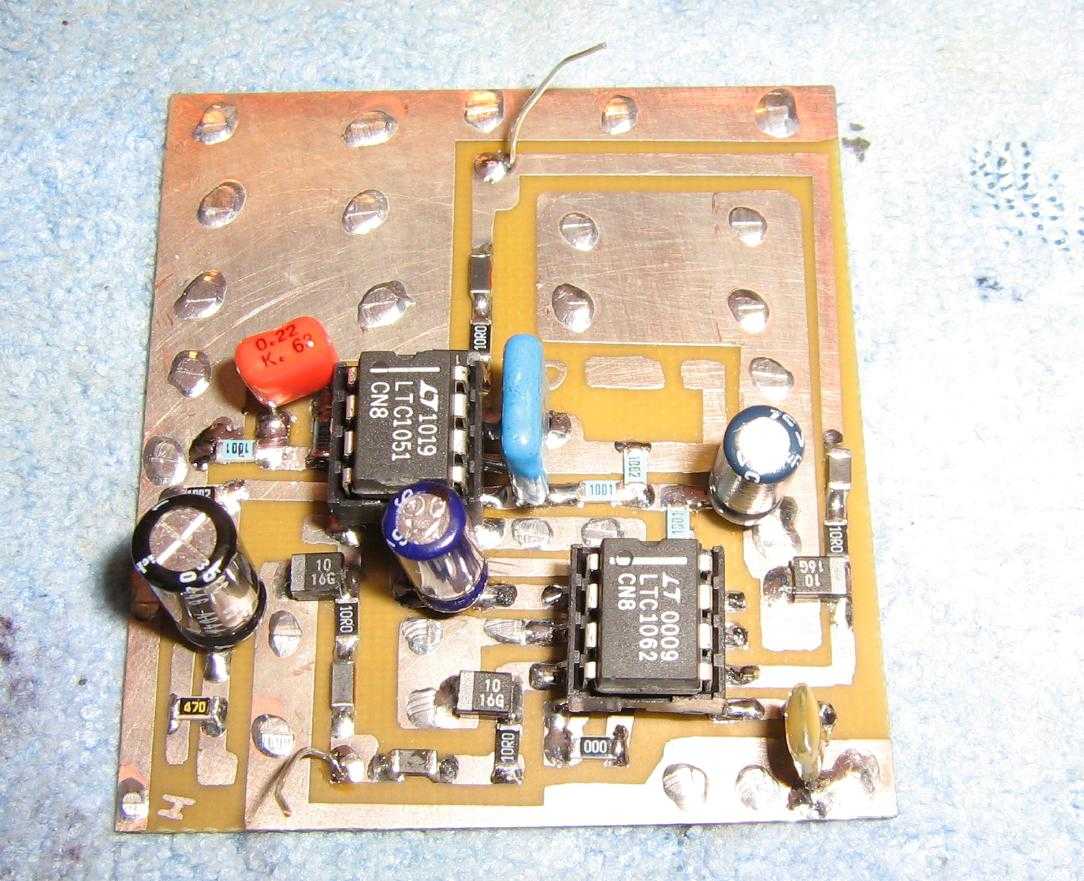
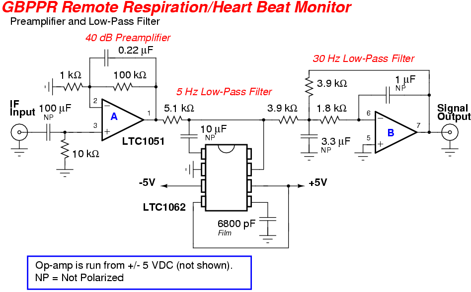
This experimental project is for a device which can be used to extract the respiration or heart rate signal from an individual by using only a beam of microwave energy in the X-band (10 GHz) region. The main circuit consists of a commercial Doppler microwave unit followed by a low-noise 40 dB preamplifier and sharp 5 Hz low-pass filter. All the signals we wish to detect will be in the sub-10 Hz region.
The contraction and expansion of the heart and lungs will impose motion on the target's chest wall. We can detect these changes as a slight Doppler shift in the reflected microwave beam. The final received signal can then be further processed to determine the frequency of these cardiopulmonary events.
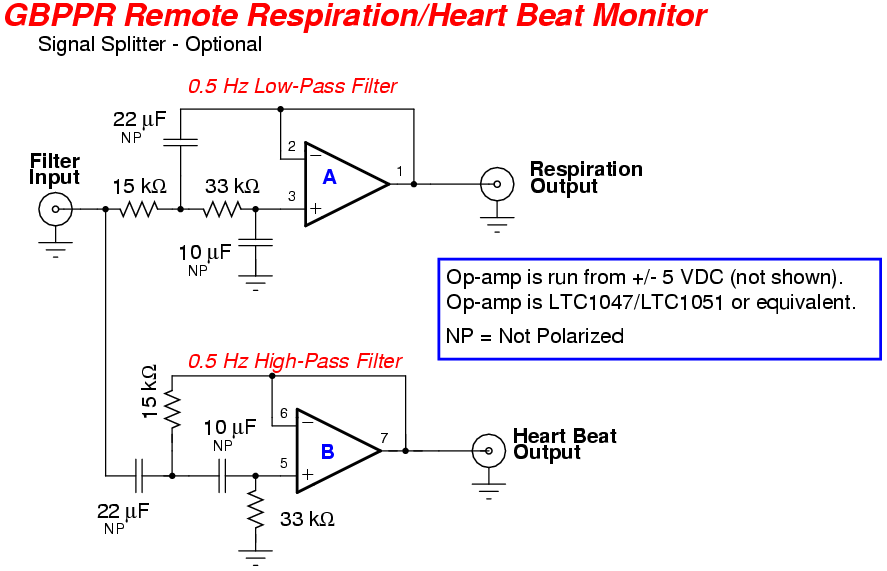
The respiration (breathing) rate will be the easiest signal to detect, as the chest cavity movement is on the order of several millimeters, compared to only the faint surface vibrations of the heart beat. Medical literature lists the period of a human's respiratory rate as being between 3 and 30 breaths per minute (16-24 average), with the heart rate varying from 40 to 200 beats per minute (43-94 average). This corresponds to a possible frequency range of 0.05 - 0.5 Hz for respiration rates, and 0.6 - 3.3 Hz for the heart rate.
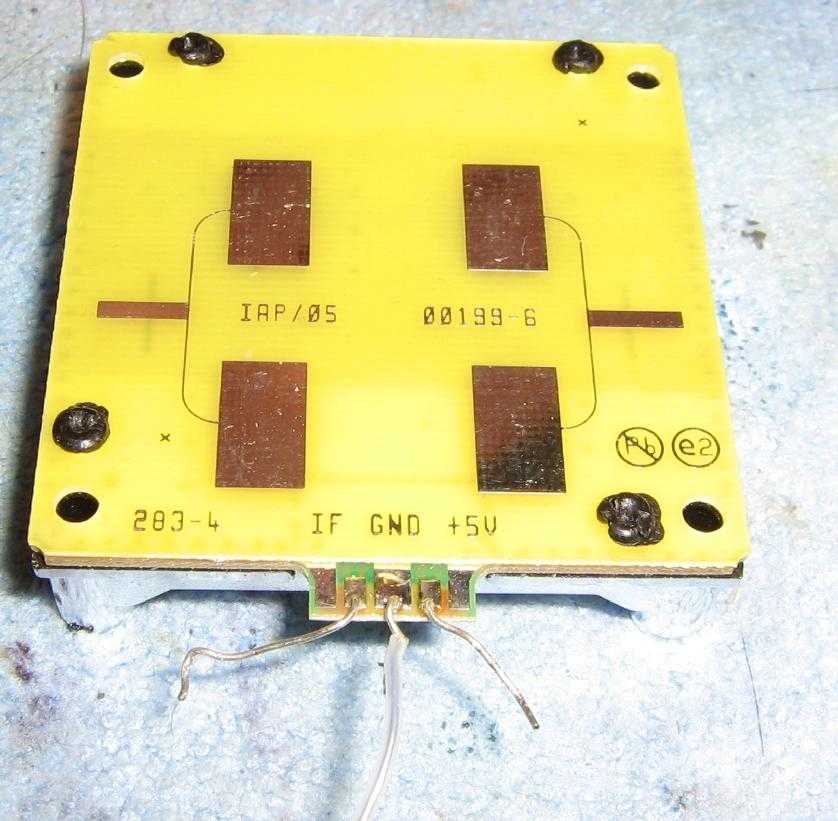
This particular experimental setup will be using a Microwave Solutions MDU1100 X-band Doppler integrated motion detector unit. These little modules require only three connections, a clean source of +5 VDC, the Intermediate Frequency (IF) output with an impedance of around 400 ohms, and ground. The MDU1100 module has built-in antennas for both transmit and receive. They operate at around 10.5 GHz and have a RF output power (EIRP) of approximately +13 dBm (20 mW). A higher powered Gunnplexer module from an old X-band police radar can also be used and will increase the overall detection range.
At 10.5 GHz, the air-skin barrier is fairly reflective to the RF energy. The wavelength of the transmitted signal will dictate the system's overall spatial resolution. At 10.5 GHz, the wavelength is 2.8 cm and the penetration depth in human tissue is only around 0.3 mm, though this seems to vary based on the medical literature I've found. Operating at higher frequencies will provide you with the ability to more easily "zero in" on an individual target, but the RF signal will be severaly attenuated by any barriers between the radiating antenna and the target. A lower operating frequency will better penetrate most barriers, but you'll loose the resolution and the antenna system will be significantly larger. All this will need to be taken into consideration if you intend to use a device like this to locate victims trapped under debris or as a Sudden Infant Death Syndrome (SIDS) monitor for newborn babies.
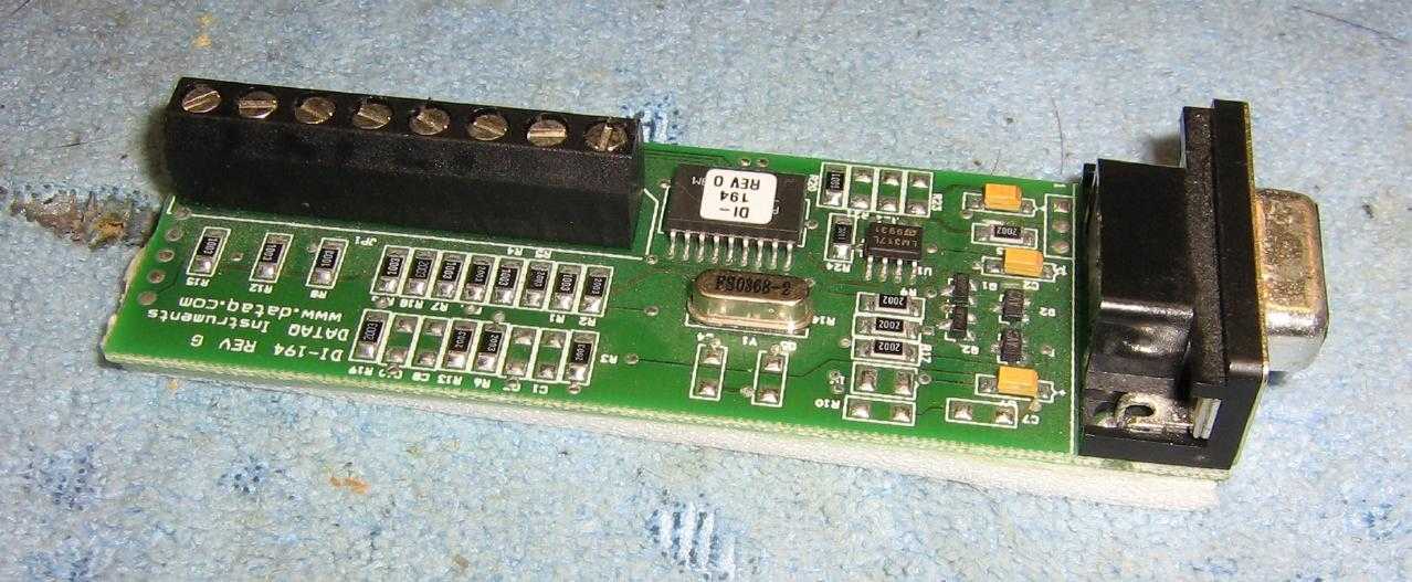
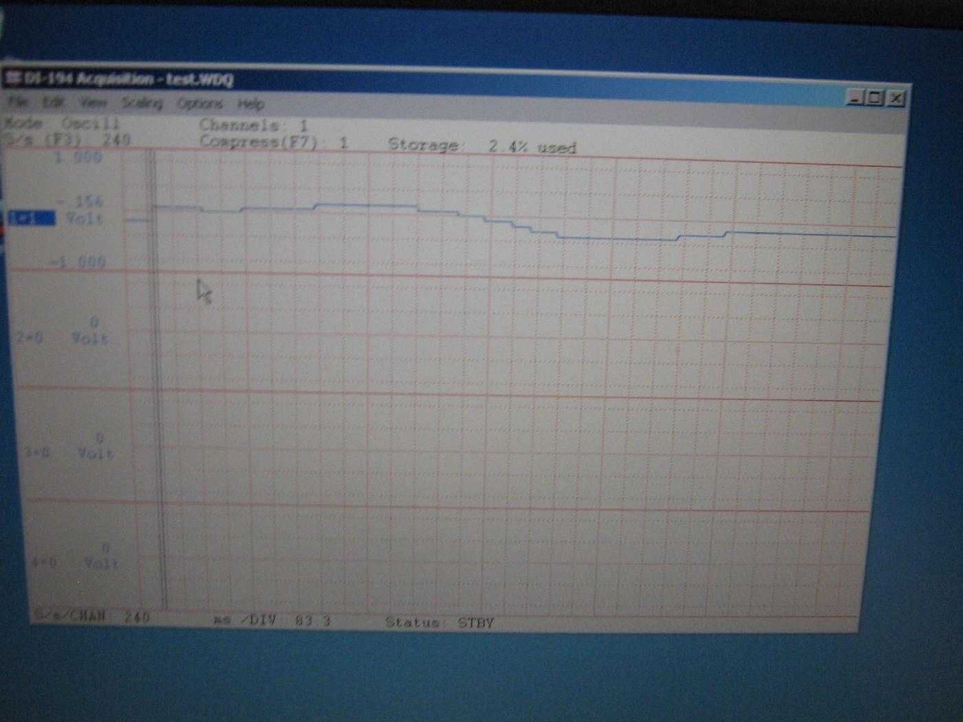
Because the final output signal will contain very low frequencies, which will not be directly "listenable" to a human being, we'll need to digitally record the signal or at least transvert it to something easier to manage. DATAQ Instruments has sevearl data acquistion boards available at fairly low-cost. For this project, a DATAQ Instruments DI-194 board will be used. The DI-194 (which is now obsolete) provides 10-bit measurement accuracy in four analog channels, has a +/- 10V analog measurement range, and up to 240 samples/second throughput. It uses a simple RS-232 serial interface which also provides power to the unit. You can use the free WinDAQ software to view and record any signals.