The Holy Grail of the amateur espionage enthusiast is a device you can point at a person (or dwelling) and record any sounds they are making. You're probably thinking "Just use a directional microphone, dumbass!" But wait, there is something out there even more advanced...
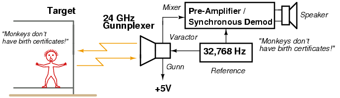
Since the late 1940s, the U.S. embassy in Moscow has been under a constant barrage of high-powered microwave energy. Conspiracy theories aside, the idea is that audio within a target embassy office will cause various nearby items to "vibrate," and any reflected microwave energy will also become modulated with this audio. The surveillance receiver is essentially phase demodulating the Doppler shifts induced onto the microwave signal by the slight physical motion of these objects. It works by mixing the received RF signal with a portion of the transmitted signal and greatly amplifying the final output. Modern devices of this type, operating at millimeter wavelengths in the 60+ GHz range, can literally fit in the palm of your hand. Information on their operation (and manufactures) leaks in from the "black" world when you study remote heartbeat monitoring equipment. One advantage to using millimeter wavelength microwave energy is the very narrow beamwidth (and high ERP) you can obtain. This will allow you to sweep the target location for any audio "sweetspots."
It is even possible to directly illuminate the larynx of the target person you are trying to listen to. The raw audio output sounds very muddy (and rectified), and you will also hear some human "internal noise," but the convenance of remote stand-off operations more than makes up for any disadvantages. Oh, and another thing... Those audio noise maskers used to "secure" certain locations with a blanket of white noise will have little effect on a surveillance device of this type. If you can illuminate the target's larynx/body directly, the returned Doppler shift will be greater (due to the physical motion) than that of a noise-emitting speaker just a few feet away. Laser-based interferometric surveillance systems are easily defeated by this method of noise masking, whereas RF-based devices shine - and can also go through walls...
Our microwave interferometric surveillance device will be based around a common 10 or 24 GHz Gunnplexer. Higher frequencies (smaller wavelengths) will give much greater performance, but signal sources at those frequencies can be difficult or expensive to find. Old police radar guns are a perfect source for obtaining X-, K-, or Ka-band Gunn diode sources.
The Gunnplexer and horn antenna will be mounted at the focal point of a surplus 18-inch DISH Network satellite dish to provide an additional gain of 30 dB or so. The mixer output from the Gunnplexer will go through a series of low-noise pre-amplifiers before being synchronously demodulated via a lock-in amplifier. The output will then be low-pass filtered and sent to a standard headphone audio amplifier. A little trick we'll be using to increase the performance of this device is to modulate the transmitted RF carrier with an ultrasonic (32,768 Hz) tone, and then use that same tone as a reference for the lock-in amplifier extracting the phase-modulated target signal. By using a lock-in amplifier, it should be possible to achieve a signal-to-noise ratio of 100 dB or more. That is equal to picking out a signal in noise 100,000 times greater than the target signal.
That's the idea at least...
This whole idea is still very experimental and will be a continuous "work-in-progress." We'll be sure to make note on any future updates.
The operating range is still quite poor, only a few feet - or even inches - in some cases. The way around this is to increase the radiated power. The device used by the Russians is said to put out thousands of watts of RF power and has been known to sterilize people inside the embassy. Oops!
The lock-in amplifier portion of the circuit, which is actually optional, does appear to significantly reduce the effects of outside interference on the target signal, especially the 60/120 Hz hum from the oscillating plasma in fluorescent lights. Note that surveillance devices of this type are typically swamped with low-frequency audio noise, so high-pass filtering is recommend before any gain stages. Also, lock-in amplifiers usually have a lead/lag phase control for their reference. Not sure how to do that, yet.
Gunnplexers with dual IF mixer outputs can even be configured for a "binaural" setup. This is a clever way to "trick" your brain into thinking you are listening to sounds in a 3D space. Since most dual mixer Gunnplexer's already provide the proper 90° phase shift of the local oscillator signal, all you'll need to do is make two separate pre-amplifier stages and run them into two separate speakers configured into a makeshift pair of headphones.
You'll also like to know that state-of-the-art devices of this type can receive the "modulated" 95 GHz radiation your body naturally emits. That means their operation is completely passive, no transmitters to detect!
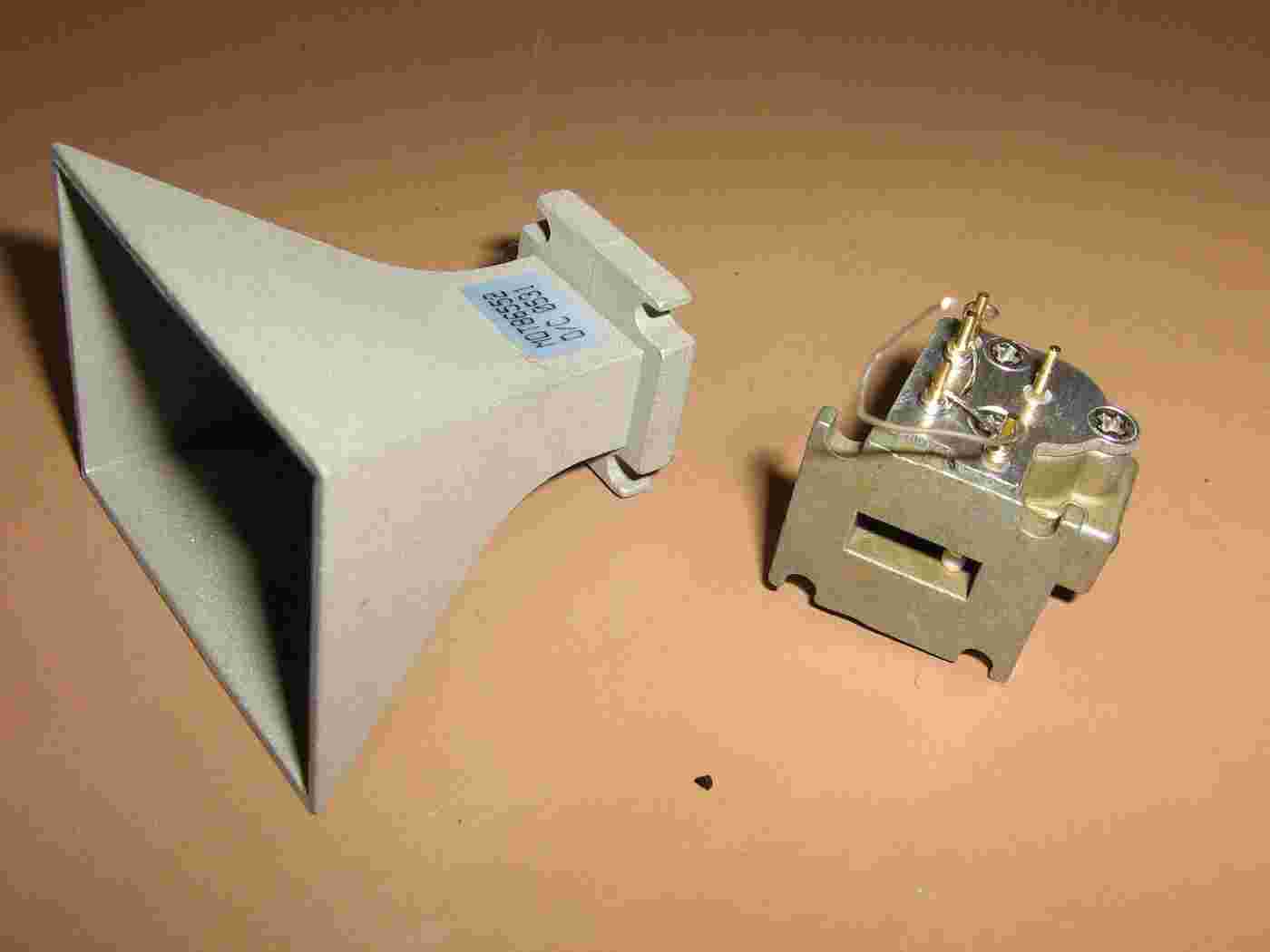
24 GHz Gunnplexer and matching horn antenna.
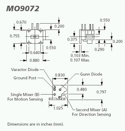
The Gunn source is a Microsemi MO9072 Voltage Controlled Transceiver. We'll be using the common term "Gunnplexer" to refer to this module. It puts out around 5 mW at 24 GHz with a +5 VDC (150 mA) power source. It has as varactor diode for electronic frequency tuning or input modulation. It also has dual mixer IF outputs, which are handy for use in radar applications.
The pyramidal horn antenna is a Microsemi MDT86552. It covers 18-27 GHz and has around 17 dB of gain.
The two mixer output pins are tied to ground (when not in use) to protect the sensitive mixer diodes from static zaps.
When in stock, you can order the Gunnplexer and horn antenna from SHF Microwave Parts Co. (www.shfmicro.com)
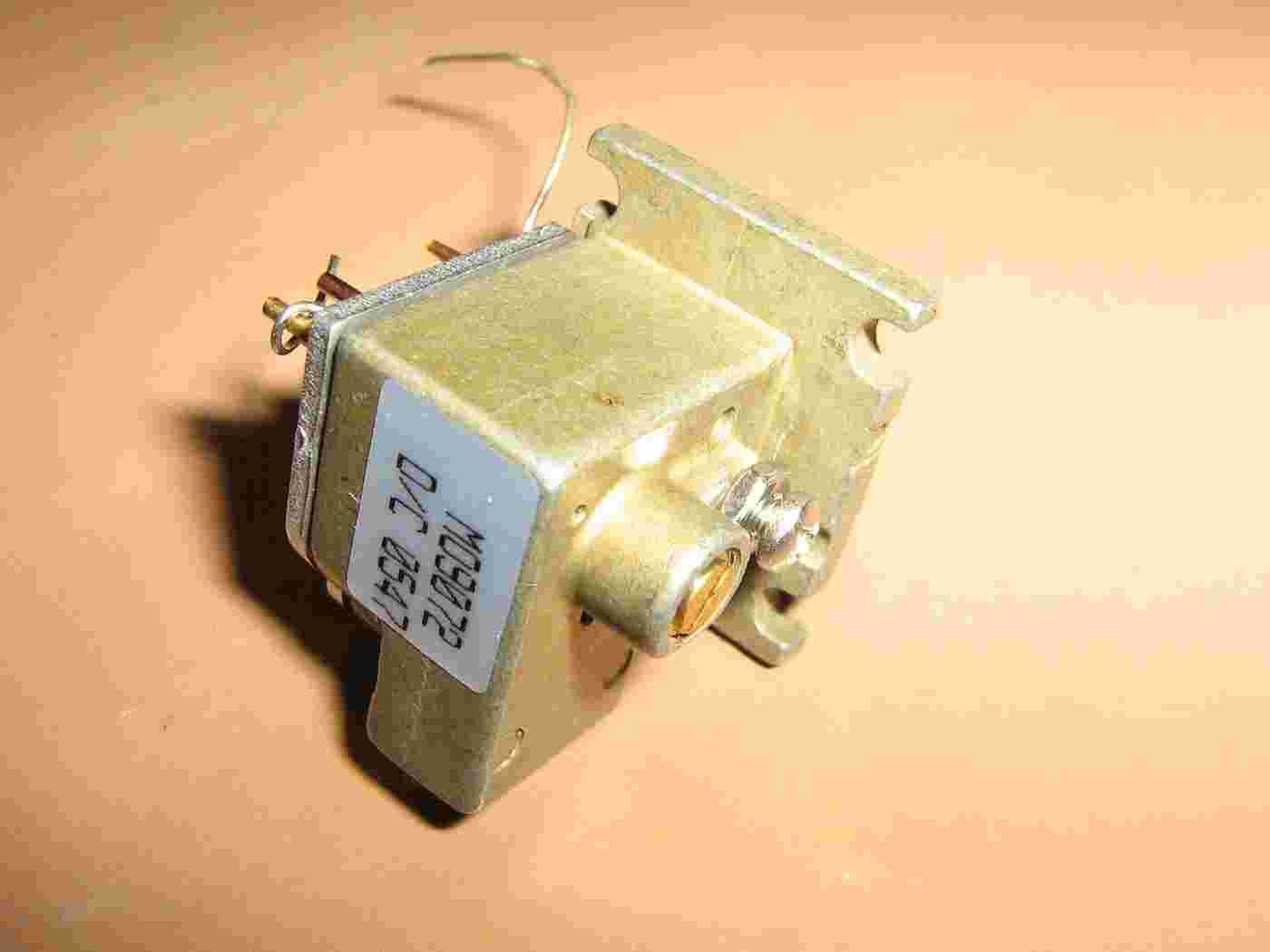
Close up of the Microsemi MO9072 Voltage Controlled Transceiver.
Note that there isn't really any way to mount it!
Close up of the Microsemi MO9072 Voltage Controlled Transceiver.
The back of the module has been polished using some 1000-grit sandpaper so a threaded bolt can be epoxied the the module's body. This should allow for easy mounting at the focal point of the dish.
Protect the waveguide cavity opening with a bit of painter's tape.
One inch long #8 brass mounting bolt epoxied to the back of the Microsemi MO9072.
The head of the mounting bolt was also polished flat.
Attach the horn antenna to the Microsemi MO9072 using #4 stainless steel or brass hardware.
Stock DISH Network low-noise block downconverters (LNB).
These will be used as a mounting bracket for the Microsemi MO9072 and its associated electronics.
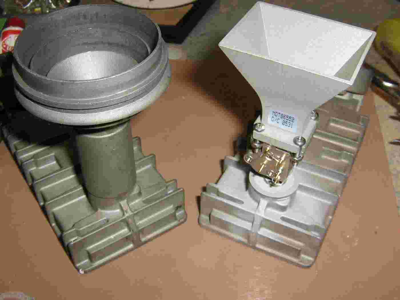
Side-by-side comparison.
The focal point should be just slightly inside the feedhorn opening.
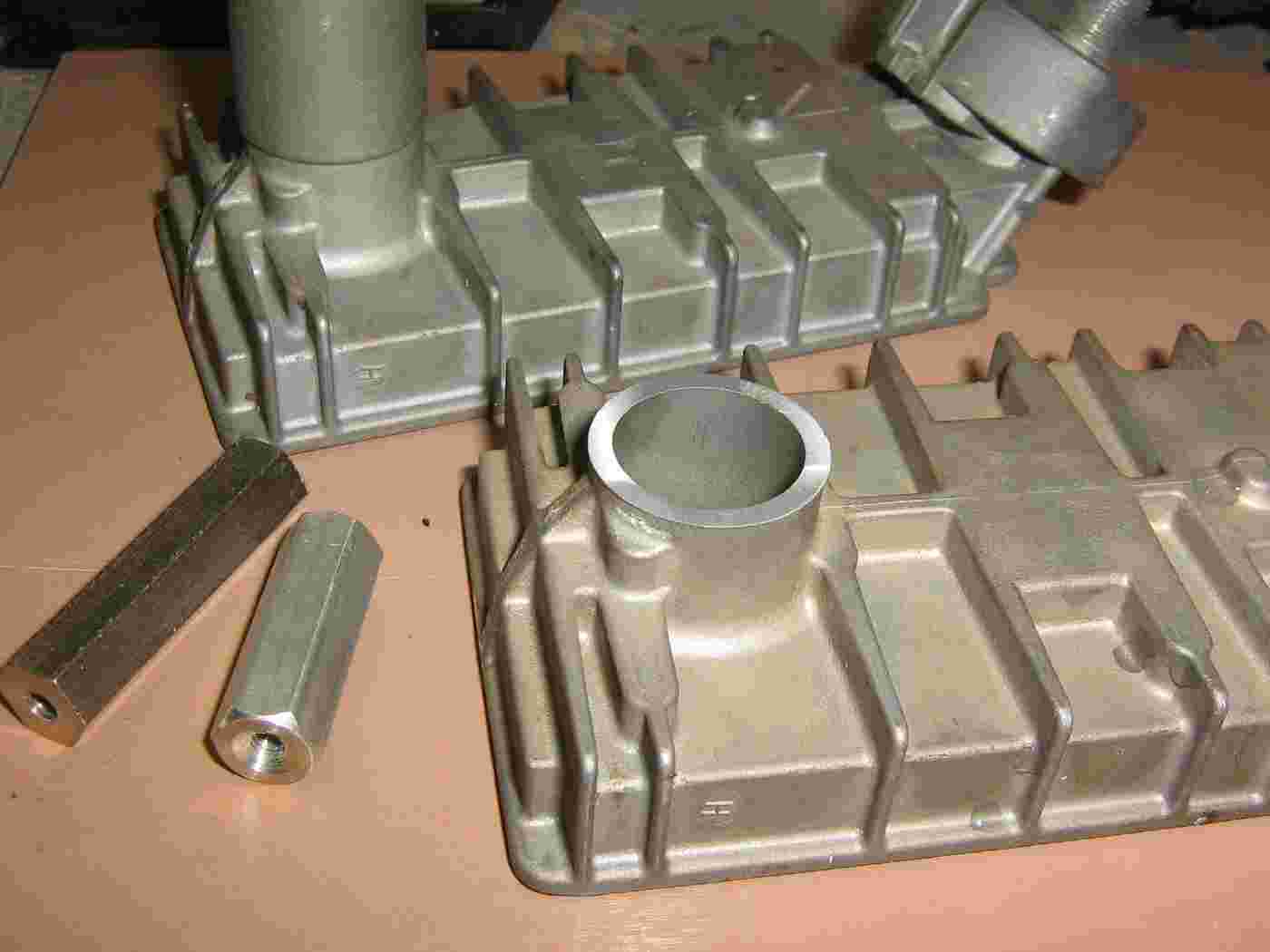
Cut and file down the center waveguide section on the low-noise block downconverter as shown above.
A #8 threaded standoff (left-side) will be placed inside the center of the hollow waveguide section. The Microsemi MO9072 will attach to this standoff.
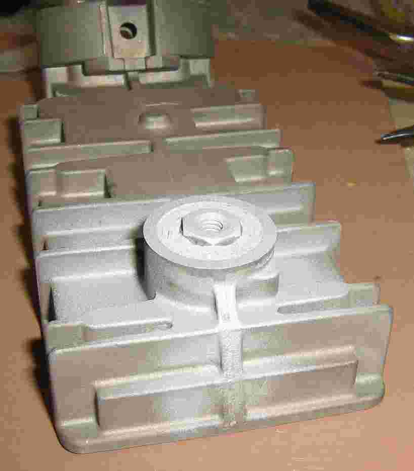
Fill the hollow waveguide section with some 2-part epoxy putty, drill it out, and epoxy the threaded standoff into the hole. Cut the threaded standoff, if needed, so it fits flush.
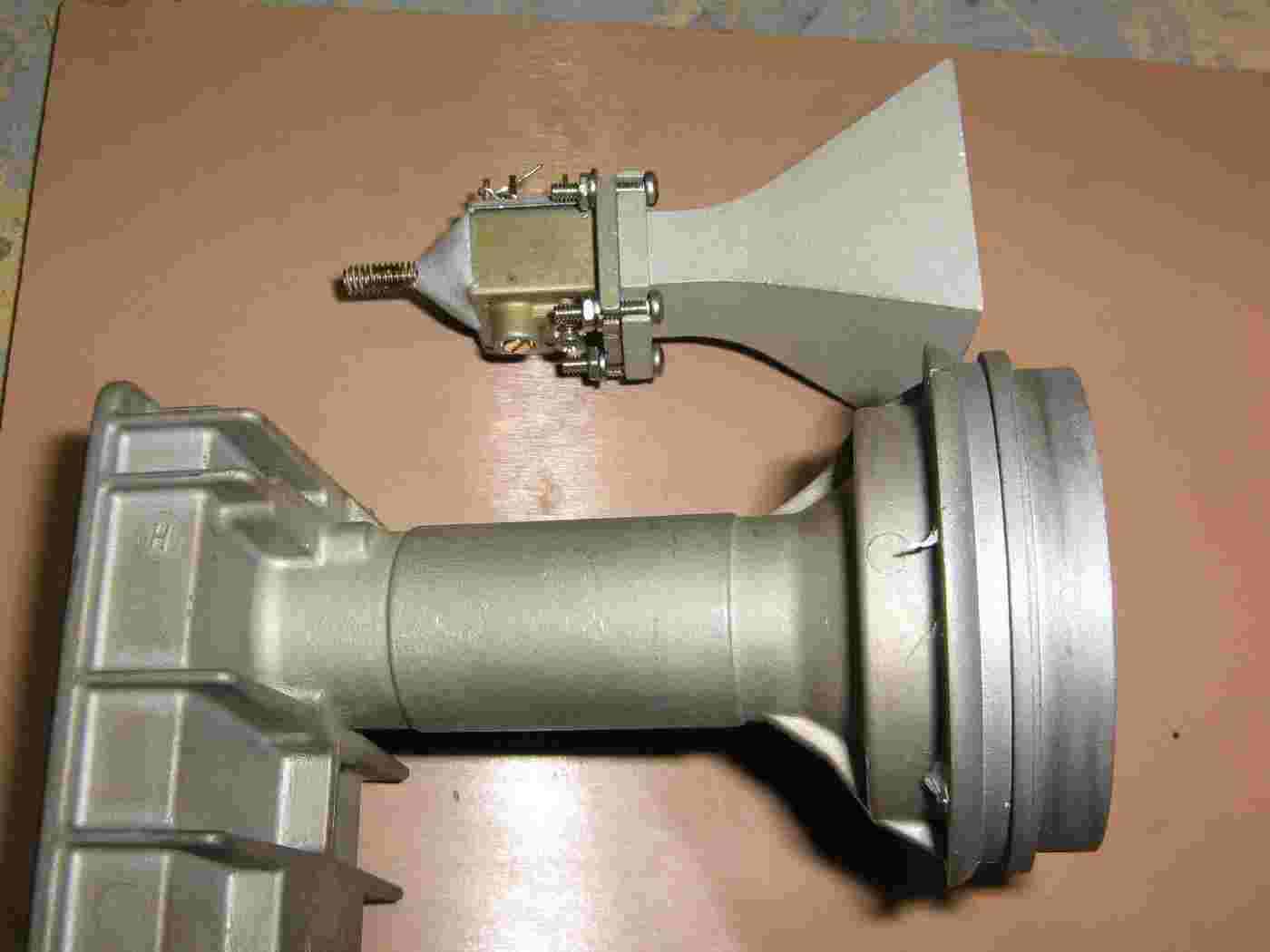
Finished side-by-side overview.
Shows what you are kinda aiming for in the end.
The threaded rod allows you to slightly adjust the dish's focal point location into the feed horn.
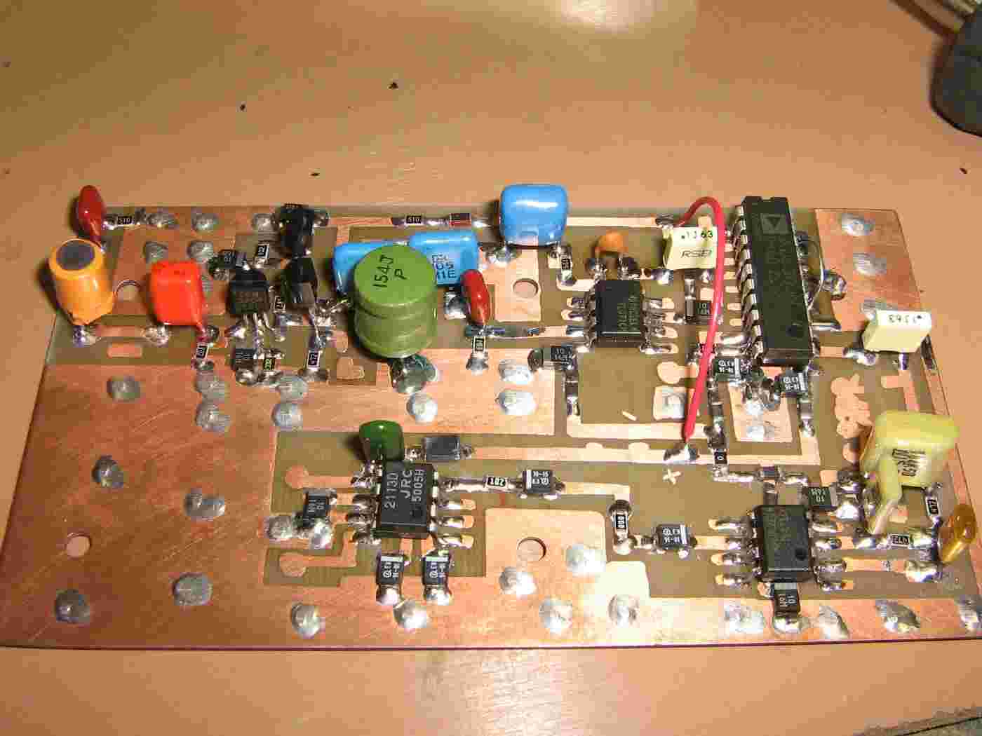
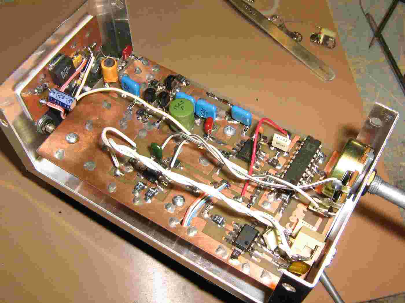
Low-noise pre-amplifier and synchronous demodulator board.
The Gunnplexer's mixer input is on the left. Some Gunnplexer mixer's like to have 2.2 kohm resistor to ground for loading. Experiment with different values to see if it lowers the noise floor.
The input pre-amplifier is based around Rick Campbell's direct conversion receivers often seen in QST. The pre-amplifier's common emitter transistor is biased for a 50 ohm input and around 40 dB of gain. The signal passes through an audio diplexer and a low-pass filter set at 50 kHz. Not sure on the output impedance of the Gunnplexer's mixer diode, but it's usually low. The second transistor is set to drive a 500 ohm impedance high-pass filter with its cutoff set at around 300 Hz. The signal then passes onto the first TL071 op-amp which amplifies the signal by another 37 dB.
The output of the first TL071 drives an Analog Devices AD630 synchronous demodulator wired as a lock-in amplifier. The synchronous demodulator's reference signal is tapped from the 32,768 Hz modulating signal on the Gunnplexer's varactor diode.
The output of the AD630 passes through a TL071 op-amp configured as a 3,000 Hz low-pass filter. The signal then drives a JRC NJM2113 (or MC34119) headphone amplifier where it is amplified another 30 dB or so. A 10 kohm potentiometer controls the gain/volume of the NJM2113.
For maximum dynamic range, power the circuit from a clean +/- 12 VDC power supply.
Components and parts layout in the picture will vary from the schematic due to constant tweaks.
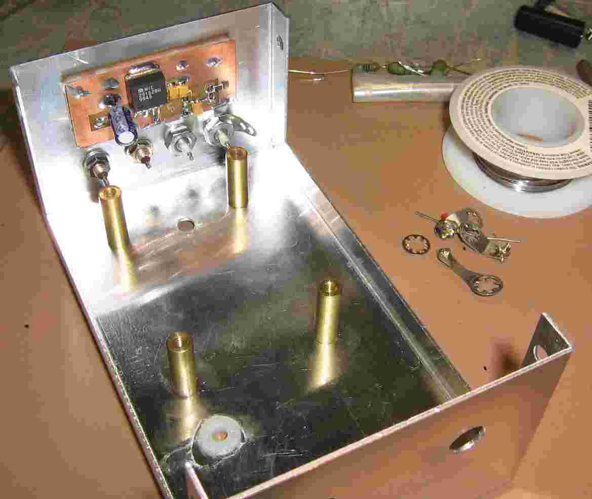
Case overview.
The Gunnplexer's voltage regulator board, based around a Micrel MIC29152, is shown mounted to the case via double-sided tape.
Try to use a single-point ground for this project to reduce interference from ground loops.
Below the voltage regulator board are the feed-through capacitors for the MO9072's connections. Note that the feed-throughs for the two mixer inputs are not capacitors, but straight feed-through connectors.
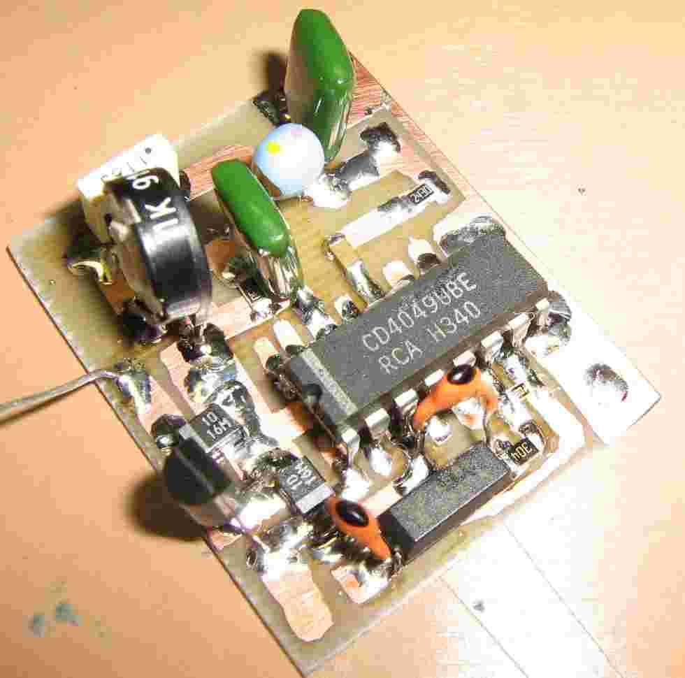
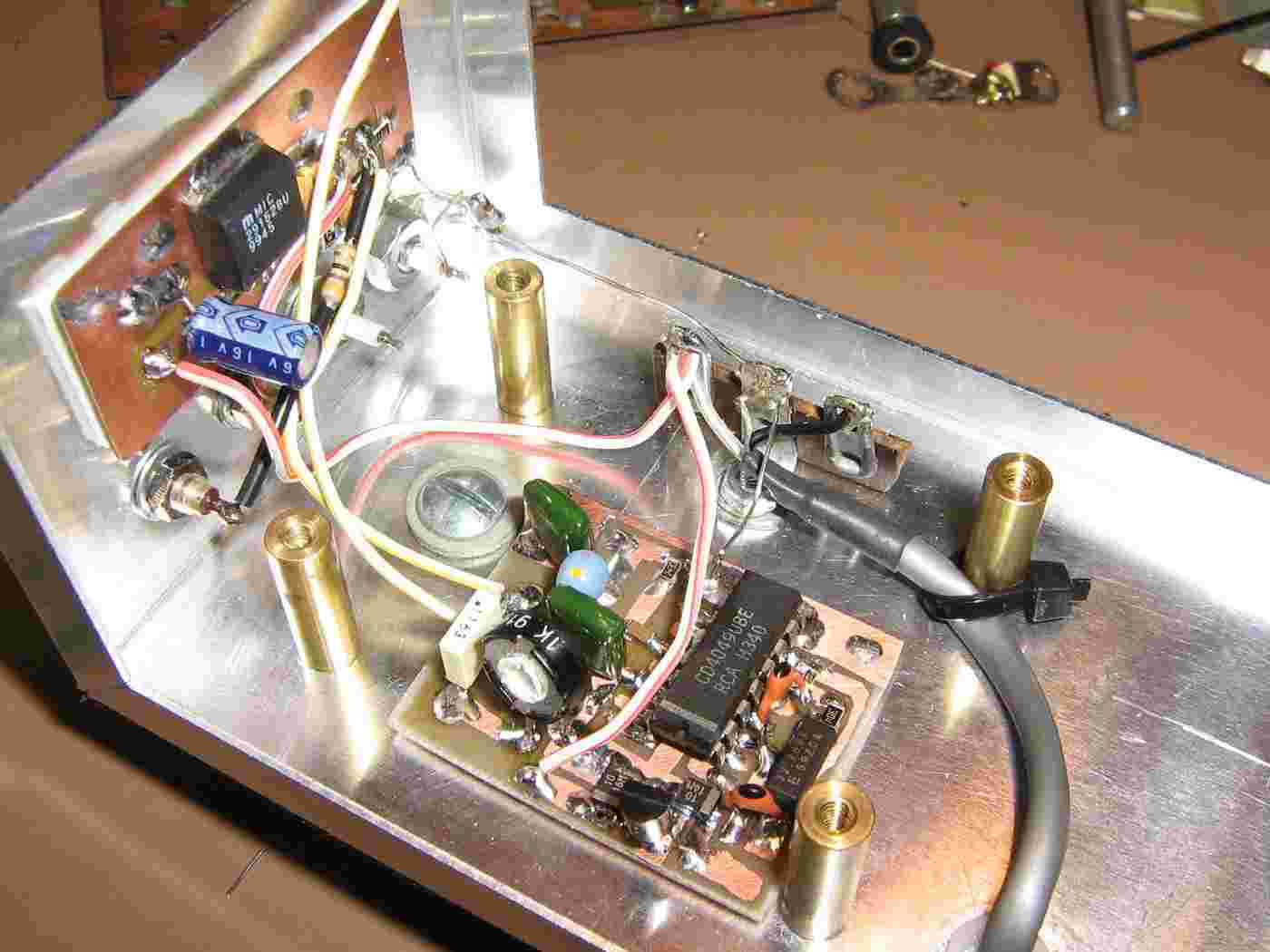
32,768 Hz reference oscillator board.
This board consists of a standard 32,768 Hz clock crystal buffered by a CD4049 to form a square-wave oscillator. The square wave output of the CD4049 is then low-pass filtered to make a nice stable sine wave.
This sine wave then modulates the MO9072 (via its varactor diode) and serves as a reference for the AD630 lock-in amplifier.
It is "remote modulation" of this reference signal which we are trying to extract as our target audio. Any signals not in phase with this reference signal are attenuated by the AD630 lock-in amplifier.
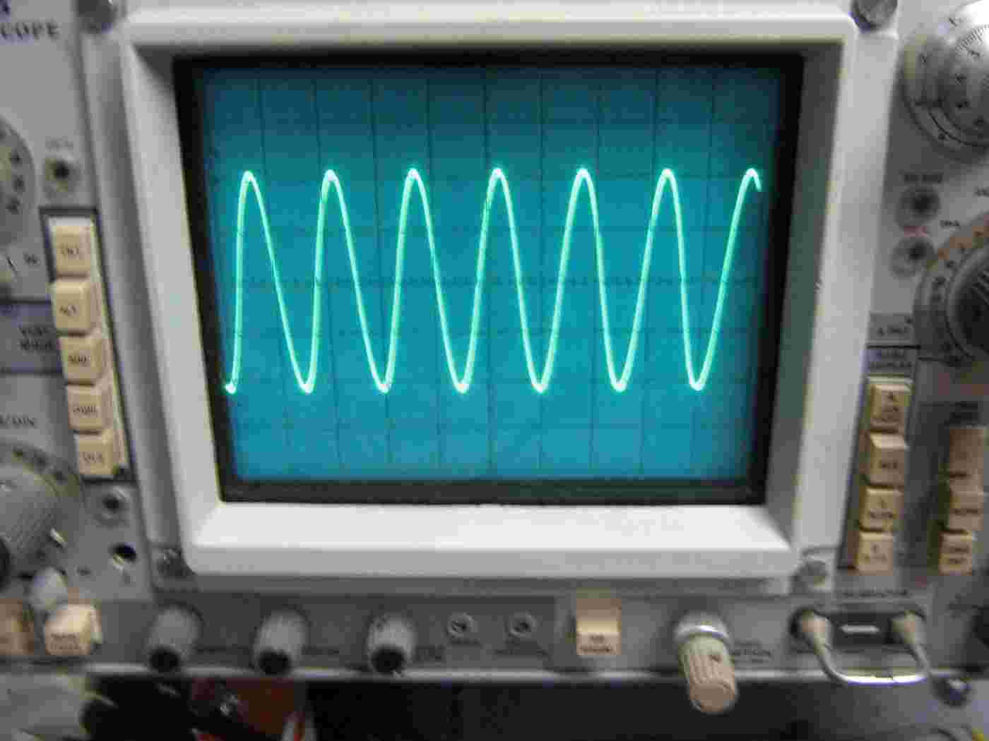
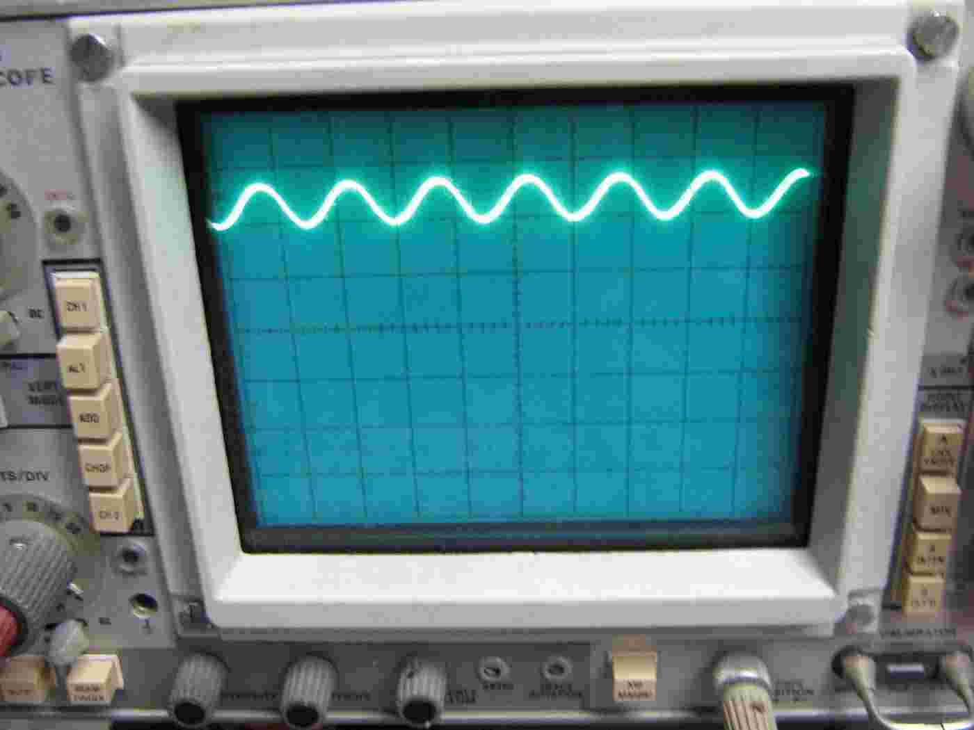
Output of the 32,768 Hz reference oscillator. 0.2 volts per division.
Gunnplexer varactor diode bias line.
The 32,768 Hz reference oscillator signal is riding on a 2.5 volt DC offset.
Not really sure on the required peak-to-peak voltage level of the input reference signal, so you'll have to play around with that one a bit.
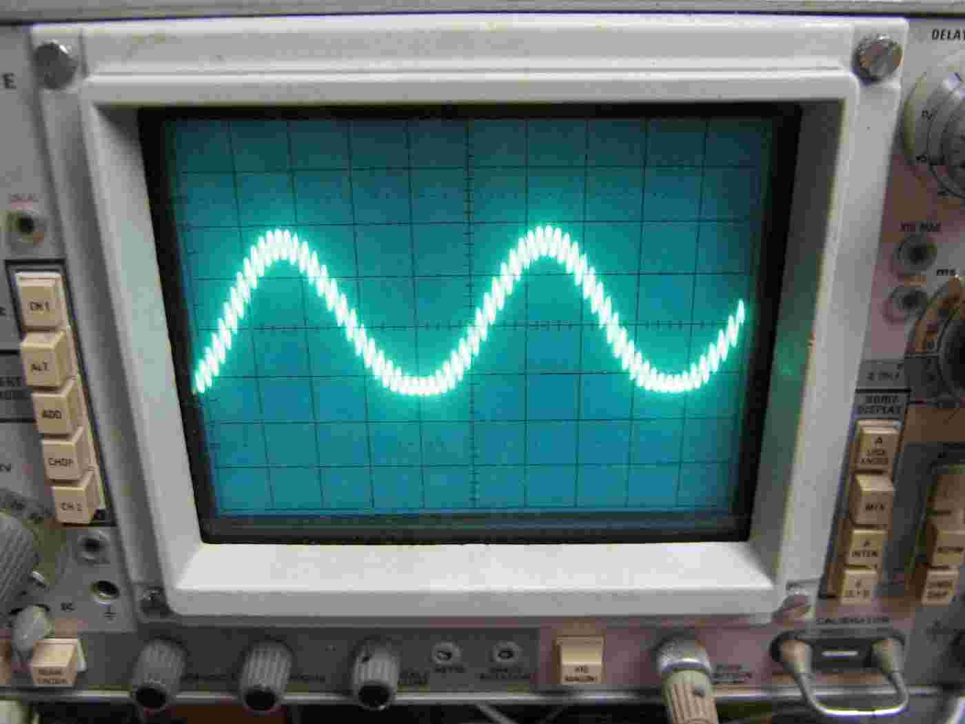
Test output of the AD630 lock-in amplifier before any low-pass filtering.
A 1,000 Hz test tone into the pre-amplifier's input is riding on the AD630's 32,768 Hz reference oscillator signal.
This signal will then be low-pass filtered to remove the ultrasonic reference frequency, leaving only the target audio.
Mounting the 32,768 Hz reference oscillator circuit board.
The DC power input cable is on the right. It runs through a drilled out F connector on the LNB.
Construction completed.
The 10 kohm volume/gain potentiometer and headphone output jack are on the right.
Note that the NJM2113 can oscillate, in some cases, if any of the connecting wires are too long. Twist the wires to help prevent this.
The above picture shows the NJM2113 wired differently from the schematic (variable feedback gain), but the schematic version is correct.
Gunnplexer wiring.
+5 VDC to the Gunn diode, the DC offset and 32,768 Hz reference signal to the varactor diode, and a mixer output. Be sure to use shielded wiring for the mixer output connection.
There should be a resistor/capacitor "snubber" circuit on the Gunn diode voltage line to prevent it from oscillating.
Both mixer outputs appear to give the same results.
A piece of art foam isolates the LNB from the case to maintain a single-point ground.
Test mounting on a DISH Network satellite dish.
The 3 dB beamwidth will be around 2°.
There are all sorts of parameters to take into account when mounting a feed horn antenna operating at 24 GHz. Since we can't really control most of them, just aim for something that looks resonable when compared to the stock setup. Ideally, you'll want to tune the focal point so the feed horn illuminates the dish for maximum efficiency and minimum sidelobe radiation.
Since these particular satellite dishes operate with an offset feed, they'll need to be tilted forward for a horizontal path. Aim the device at a fan while listening with a pair of headphones to determine the proper tilt angle.
The overall performance of this device will usually follow the standard "radar" equation. That is, to double the operating range of this device, you'd need to increase the output power sixteen times.
When in doubt, use more power!
Test aiming setup.
A Nidec Beta SL muffin fan powered from a 12 volt battery was mounted 49 inches off the ground.
The distance back to the dish was 12 feet.
28° required tilt angle for a DISH Network "500" parabolic dish to get a fairly horizontal beam. Note I replaced the smaller "300" series parabolic dish with the larger "500" version. Not sure if this changes the focal point.
Distance from the floor to the RED dot was 46 inches. Distance from the RED dot to the BLUE dot is 6 inches. Those magnetic tilt indicators are available at Harbor Freight Tools.