There have been recent reports of "insurgents" intercepting unencrypted U.S. Predator drone video feeds in Iraq and Afghanistan. The Predator drone video feeds were sent - in some cases - from the drones without any encryption technology. The insurgents were in a rather simple situation to intercept and monitor these video feeds, and also save them to share them among each other.
A Wall Street Journal article states that a software package called SkyGrabber was used to intercept the video feeds. The original intention of this software is to decode images and video feeds "off the air" by using standard satellite receving hardware and antennas.
After doing some research on the issue, we found that within the Predator video feeds (aside from the image data) there is also mission control data carried inside the satellite signal which is sent to the ground control stations. It is theoretically possible to read off this mission control data both in the real-time intercepted video feed or from a recorded video data feed.
There is a command and control link to communicate from a control station to the Predator drone. Further, there is also a data link that sends mission control data and video feeds back to the ground control station. Here, one has to distinguish between line-of-sight communication paths and beyond line-of-sight communication paths.
The operation of the line-of-sight link is limited to approximately 81 to 138 miles. This operating range can be extended, for example, by using mobile ground control stations which are locally deployed. Line-of-sight links are critical for takeoffs and landings of the drone. These links utilize a C-band (4.4 - 4.94 / 5.25 - 5.85 GHz) communication path. Beyond line-of-sight communication links operate in the Ku-band (14.40 - 15.35 GHz) satellite frequency. This allows the Predator to cover approximately 1,500 miles of communication range capability.
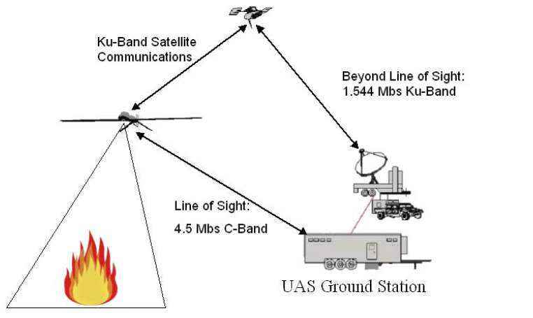
Figure: C-band & Ku-band Communication
This explains why the insurgents were able to intercept the Predator video feeds when they were sent unencrypted to the ground station. The only hardware required is a standard C-band or Ku-band satellite receiving setup. Transmitting traffic to a satellite is not needed in this case.
The drones normally use MPEG Transport Stream (MPEG-TS) to send video and data to the ground station. MISB (Motions Imagery Standards Board) has developed several standards on how to embed the control data into MPEG streams.
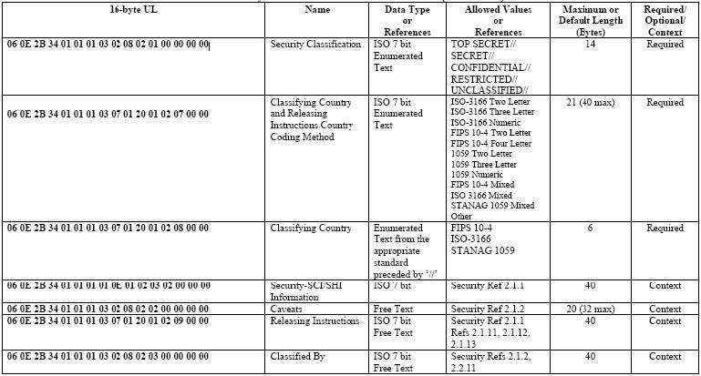
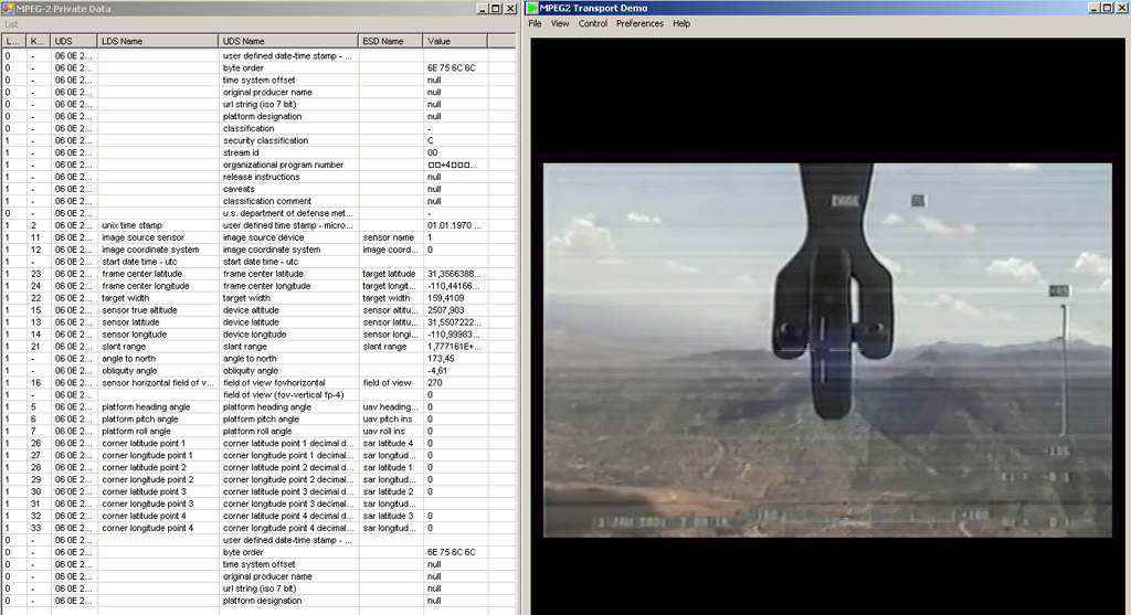
Figure: Example of Metadata Sent with the MPEG Transport Stream
An important note is that our research shows that most, if not all, metadata within the MPEG video stream is not encrypted - if the MPEG stream itself is not encrypted.
During our research, we found a suitable tool to read the mission control data from the video feeds and also from any saved video feeds. The tool is programmed by LEADTOOLS and is capable of reading KLV metadata out of MPEG-TS. Inside the LEADTOOLS Multimedia SDK package, a programmer finds source code and binaries of the needed tool.
The following screenshot shows the tool in action. The loaded file is a saved MPEG-TS Predator drove video feed with private metadata embedded:
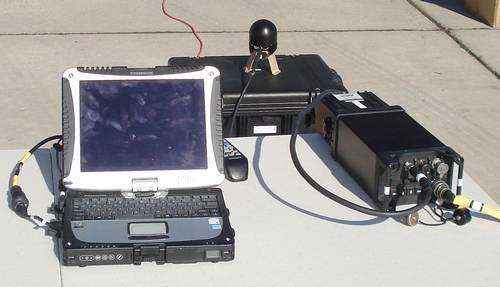
Predator Receiving Station
The Predator data link system provides command and control information from the Ground Control Station (GCS) to the UAV using the Command Link (CL) and payload data and status information from the UAV to the GCS using the Return Link (RL). The transmitter and receiver units can be software configured to perform CL or RL functions. The Predator data link system utilizes two CLs and two RLs. The data link system uses 16 bit messages. The CL-configured terminals are capable of transferring data at 19.2 kilobytes per second (kbps) and 200 kbps using Frequency Shift Keyed (FSK) modulation. The RL-configured terminals are capable of transferring either National Television System Committee (NTSC) formatted video with data subcarriers at 6.8 MHz and 7.5 MHz offset or 3.2 Mbps FSK data without the subcarriers.
The GCS contains computers, voice communications equipment, displays, and user interfaces, as well as accommodations for the pilot and payload operator. The GCS is connected to the Ground Data Terminal (GDT), which consists of the antenna system, a diplexer, a custom-built Low-Noise Amplifier (LNA), transmitters, and receivers. The antenna system contains three antennas: a 33 dBi parabolic dish, a 15 dBi horn, and a 6 dBi stacked dipole array. The parabolic dish is used when the UAV is beyond approximately 48 km in range. The horn is used when the UAV is within 48 km. The stacked dipole array is typically not used. The diplexer permits full-duplex operation.
The UAV data link system contains antennas, diplexer, computer, transmitters, and receivers. The antennas utilized by the UAV are: a 15 dBi horn, a 3 dBi stacked-dipole array, and a 0.3 dBi stub antenna. The horn is used by the primary data link. The stacked-dipole array is used by the secondary data link. The stub can be used with the primary data link, although it is typically not used. The diplexer permits full-duplex operation. The computer parity checks data, selects the optimum CL, and discards erroneous messages.
The final amplifier stage of the UAV and GDT data link transmitter can be software-controlled to switch between 1 mW and 10 watts output power. The 1 mW low-power mode is used for ground testing. The UAV transmitter will automatically revert to 10 watts if the link cannot be maintained at 1 mW.
         Transmitter Frequency: 4400 - 4940 MHz or 5250 - 5850 MHz, 1 MHz tuning steps
                Transmit Power: +40 dBm

                                LOS           DLOS          LOS          DLOS
	                        Command Link  Command Link  Return Link  Return Link
          Emission Designators: 560KF1D       88K3F1D       17M0F9F      4M72F1D
 Emission Bandwith (MHz) -3 dB: 0.34          0.063         8.5          2.8
                        -20 dB: 0.42          0.088         18.0         20.0
		        -40 dB: -             0.219         -            -
		        -60 dB: 1.2           0.671         46.2         66.0

            Receiver Frequency: 4400 - 4940 MHz or 5250 - 5850 MHz, 1 MHz tuning steps
          Receiver Sensitivity: -98 dBm (560KF1D/88K3F1D) or -84 dBm (17M0F9F/4M72F1D)
    RF Selectivity (MHz) -3 dB: 303
                        -20 dB: 375
                        -60 dB: 525
1st IF Selectivity (MHz) -3 dB: 35
                        -20 dB: 55
			-60 dB: 115
2nd IF Selectivity (MHz) -3 dB: 1 (CL)   20 (RL)
                        -20 dB: 3.2 (CL) 22.5 (RL)
			-60 dB: 4 (CL)   28 (RL)

   Diplexer Low-Band Frequency: 5250 - 5475 MHz
 Diplexer Cross-Over Frequency: 5475 - 5625 MHz
  Diplexer High-Band Frequency: 5625 - 5850 MHz

    GDT Parabolic Antenna Gain: 33 dBi, cosecant-squared illumination type, vertical polarization
   Azimuth/Elevation Beamwidth: 3/45 degrees

         UAV Horn Antenna Gain: 15 dBi, Technical Associates Model 11572, vertical polarization
   Azimuth/Elevation Beamwidth: 30/30 degrees

         UAV Stub Antenna Gain: 0.3 dBi, TECOM Associates Model 702-653-3, vertical polarization
   Azimuth/Elevation Beamwidth: 360/55 degrees

       UAV Dipole Antenna Gain: 3.0 dBi, TECOM Associates Model 702-653-1, vertical polarization
   Azimuth/Elevation Beamwidth: 360/25 degrees
