| Trunking System Analyzer | |
The Trunking System Analyzer is a "data analyzer" that works on
PL (Private Line or CTCSS) tones/freqs are identified by frequency. DPL (Digital Private Line) a low speed data stream 'underneath' a voice channel that works much like CTCSS.
This analyzer can be used as
Here is a sample of the analysis output from a PC connected
to the WPA:


Frequency Collect File - Poll Labs Trunk-Term Ver. 1.0

  Plano, TX

  Data Period: Begin: 11 PM 8-19-97
               End:    7 AM 8-20-97
               Notes: Overnight activity

  Sys Id (OSW_DATA=0x032B) = 3004
  Sys Id (OSW_exop=0x2800) = 3004
  Sys Id (OSW_ADDR=0x1FXX) = 1FC4

  Frequency (OSW ADDR 1F00)= 8666500
  Frequency (OSW exop 2800)= 8666500

  The list below is a Frequency list of *active* frequencies used in
  the system monitored for the time period shown above indicated.

  The 'Hits' column inicates the number of OSW (Outbound Status Words)
  specified as TalkGroup Assignments (and not system status or other
  overhead activities).

  Freq
  Code  # Hits  Frequency
  ----  -------  -------
  02D6    14367  866.150
  02D7    15850  866.175
  02EA     4220  866.650
  02EB    16394  866.675
  1335    12483  867.150
  0336    15145  867.175
  03CA    15952  867.650
  03CB        0  867.675  DVP capable *analog and DVP observed 8-13-97*
  03E3    16057  868.275
  03E4        0  868.300  DVP capable *analog and DVP observed 8-13-97*


  The list below is not a comprehensive Talk Group list of Talk groups
  on this system but rather is a list of Talk groups active on this
  system for the period indicated.

  Talk
  Group  # Hits       Notes
  ----  -------     -----------
  0170     9309     FD Dispatch
  0190      961     FD Ch F
  01D0    35037     PD Dispatch
  01F0     7144     PD Ch A
  0210     3145     PD Ch B
  0230     3051     PD Ch C
  02B0      925
  0330    28388     PD NCIC
  0350      332
  0358       25
  0530       69
  0670       36
  06D0       38
  0990       69
  09F0       42
  0A30     4611
  0AB0      375
  0AD0      286
  0CB0    15901     Wylie  PD 1
  0CD0      338     Wylie  PD 2
  12E0       12
Interface boards will be available for such common scanners as the PRO-2006, BC-760XLT, BC-3000XLT and the BC-855XLT. Two RS-232C output ports on the rear panel allow interfacing to a PC for data analysis (such as importation into a spreadsheet or data base program) AND control of other products.
A 'PC' is encumbered by so many other 'housekeeping' activities that it can't be depended on for time critical data acqisition. The solution was to embed a micro in the WPA and move the responsibility to it. The WPA also contains several filters and a 'center slicer' for processing the received signal so as to be more robust when received signals are weak or in the prescence of noise. I also 'phase track' (in software in the micro) the incoming data bits and therfore assure that I'm always sampling 'mid bit' - not just watching edges then sampling whatever represents data as some of the PC-based routines that are making there way around the web do.
1) the 'High Speed' Trunking CC (Control Channel) data.
2) the Low Speed data which underlies the voice once the TC (Trunking
Controller) has assigned mobiles to operate on a
VC (Voice Channel). The Low speed data may be viewed
as DCS (Digital Squelch).
3) there is the "Disconnect Sequence" issued by the TC (Trunking Controller)
on a voice channel after a period of time when
the mobiles have stopped xmitting. This Disconnect
Sequence sends all mobiles in the 'talkgroup' back to the CC. The TSA
will recognize this signal as well and return it's
accompanying receiver to the CC to monitor for talkgroup ID's once again.
A suggestion was made - why not just make use of the OS456 (etc) interfaces available for the PRO-2006. The cost of our unit plus the OS-456 though is beyond most people's budgets BUT we will be producing a unit that will work with an existing OS-456 for those folks who have already purchased an OS-456 or contemplate purchasing an OS-456 .
Background in the design of the WPA
When a "call group" code appears on the control channel paired with a "frequency code" the user's radios set for that 'call group code' will move to a voice channel to communicate.
The 'call group code' would be a be fleet, sub fleet, etc call group code. Unit to unit calls can also be made on a Motorola Trunked system and these are identified by the setting of the "Individual call bit" on the trunking control channel.
Design and Interface of the TSA.
An example of an Interface board mounted in a BC760XLT and in a Interface board mounted in a PRO-2006 .
Trunking Operation on the TSA
All commands are selected via menus selected and scrolled on the LCD
display.
Track
Call Groups Menu
Lock-Out
Edit Menu
TCC
data Loging Menu
Here are some other miscellaneous 'data captures':
One solid minute of _ALL_ trunked data on the Plano, Tx Type II logged Tuesday 5-20-97.
One solid minute with only meaningfull data on the Plano, Tx Type II System using the built-in data screening feature on the TSA. This feature weeds out background words and other meaningless data allowing only Talkgroups and their associated freq code through. This mode is very valuable in logging _only_ active talkgroups without the annoying clutter. Through time-in-type we learned which 'data' to ignore for this feature.
Plano, Tx
Freq codes (a Type II system) (old data)
Plano, Tx
Call group codes Type II system (Several new groups added since this
was put here)
Arlington,
Tx Freq codes a Type I
Allen/McKinney,
Tx Call group codes Type I system (Allen and Frisco have since moved
to the Plano system)
Trunk Tracker/GMSK data demodulator
Another one that never made it into production (although several protos are still in daily service!).
Let me tell you, there is NOTHING quite like writing 'your own solid code' and being able to 'see' ALL the trunking data without having to have blind faith in someone else's 'product' effort or backyard 'hack' described loosely in newsgroups by self-proclaimed 'lords' of hacking. One of the more memorable times in my life is when I first 'locked the loop' and tracked my first trunk groups in about 1992 (this was YEARS before commercial product was offered to the consumer!).
This was before I had incorporated the "rate 1/2 convolutional error correction code" routines too (much like as seems to have been done in the RS PRO-91; it falses regularly) and 10-bit 'block' parity check (normally performed over the received and 'error corrected' data to verify it 'corrected' okay) - it worked (example of early code) but was subject to some falsing occasionally. This would take the form of going to a 'channel ' or responding to a TG 'assignment' that didn't exist (owing to one or more bits errors in the received trunking control channel data LIKE the PRO-91).
Serious time and effort went into developing this item and I can't begin to describe the hardware and software co-development process that took place involving the intertwined use of a real-time 24-channel HP logic analyzer, several multi-channel real-time O-scopes (triggered at times by the logic analyzer to view the waveform present during a particular stage of data procerssing or to indicate the occurance of a critical interrupt), an EPROM emulator (loaded with the object output from the assember running on the development/compiling PC) and pulse-delay/pulse-stretch generators as well numerous 'software hooks' that could be caught by the logic analyzer and thereby indicate program logic state and data processing/ECD progress.
The box, when added to a scanner such as the Radio Shack Pro-2006 or Uniden BC760XLT demodulates 'wireless' data (of the GMSK variety) and formats it internally for analysis or "talk group" comparing against an internal list of desired 'talk groups' or outputs the data for further processing and logging to a PC. As such this box can be used as trunking design tool, as a system analysis tool (count the occurance of each and every different command capable of coming across the system) or as a learning aid (easily demonstrating the operation of a 'trunked' radio system within the context of an easily understandable conventional programmable VHF/UHF FM 'scanner').
The intent was to make this box was able to be added to a number of different scanners. It has two RS-232 ports for outputting data to a PC or receiving commands. Set up and control locally on this box is via front panel 'joystick' keys and the menu appearing on the alpha-numeric LCD display.
Accompanying software was written for the PC to allow viewing in real-time ALL data appearing on Motorola Type I and Type II analog trunking systems.
- Trunk Tracker page, shows some early hardware and describes it's basic operation.
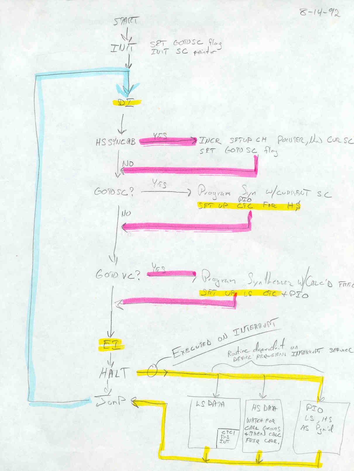
- Main program 'Loop' - shows how main 'routine' responds to interrupts and then circulates though a series of flag-checks to determine the next course of action such as perform a mode change from setup channel to voice channel or vice versa.
- Main program 'code' - early code (circa 1993) prior to major program restructuring and incorporation of EDAC (Error Detection And Correction) routines such as the Rate 1/2 Convolutional Error Correction code and the 10-bit block parity code or the LCD driver routines. To view this later code you'll have to sign a non-disclosure clause (or wait until I have a clear sight of my death bed and I simply decide to post it)